Thursday, June 30, 2022

 Viking Study Essay A Very, Very Small Progress

 A Very, Very Small Progress

Excerpt from the Heimskringla Saga - "The citizens had plenty of food and whatever else they needed to withstand a siege. So Harald hit on a plan. He had his fowlers catch some little birds which nested in the city and flew out to the forest during the day to find food. Then he had chips of resinous wood, smeared with wax and brimstone, attached to the birds’ backs and set alight. The instant the birds were released, they all flew straight back to the city to seek out their young and their nests in the thatched roofs. The fire then spread from the birds to the house-thatches, which were made of reeds or straw. Even though each bird carried only a small spark of fire, there was soon a huge conflagration as lots of birds brought fire to thatches throughout the city. One house after another burst into flames until the whole city was ablaze.

The inhabitants abandoned the city and begged for mercy, even the ones who had often spoken haughtily and dismissively about the Greek army and its leaders. Harald spared everyone who asked for mercy and took control of the city. …" (McDonald 297).

It is intriguing to see a modern-like treatment of the enemy by vikings when no one is explicitly depicted as injured or killed in a siege, only, maybe, implied. That is not very common for a viking saga. The writer is the friendly Icelandic diplomat Snorri Sturlusson to Norway at the turn of the twelfth century. Harald refers to Harald The Hard Ruler, a future viking king of Norway at the time of the action. No one is harmed by the constraint of resources because “plenty of food and whatever else '' are available during the siege in the viking king’s early military training career (McDonald 297). The writer receives a substantial “gift” from the Norwegian royal family and discloses the gift (Byock 15). He openly declares that another saga, Lay of Ragnar, is dedicated to “honor” the gifting royal family (Byock 15). 

The besieged city in question is in Sicily, which is one thousand and five hundred miles southeast of Norway, and the year is 1038. For a diplomat to compose a summary report, Snorri succeeds in negotiating and navigating between pros and cons of accurate descriptions and empathetic condolences to reconcile all parties involved, when “asked for mercy” and “spared” are said, instead of words like “granted” by the trainee king, a prince by definition (McDonald 297). For this particular saga, the audience includes the royals of the very characters of the saga, the nobles that served the royals, and the ruled commoners. The readership is diverse, and it is a matter of checks and balances between Snorri’s light-hearted words, such as “whatever else”, on his mind and the serious, business side, work product.

In the first sentence, the siege is set in motion by the Byzantine Empire’s effort to consolidate power, to establish a hierarchical society, where piety is paramount. It has been at least five hundred years since the fall of the empire-sized Rome government to the story’s action time. Ever since the fall of Rome, the isolated, small, and unstable societies treat each other “dismissively” (McDonald 297). And countries dismissing one another can lead to wars.

From the second to the fifth sentence, as promotional material for the royal family, the military skills of The Hard Ruler appear godly resourceful, defying calculation of power of resources when local “resinous wood” is utilized as zero-cost weapon, and “little birds'' become projectors with perfect range and precision when “they all flew straight back to the city” (McDonald 297). Snorri Sturlusson’s diplomatic mission must have been successful for the hosting country to gift him. With his new generation’s novel prose, vernacular form of writing, he can speak his mind directly, not very different from twenty-first century science paper writing. 

People know that sagas often hint on the outlines of historical facts, and outright trivialization can add insults to injury. So near the ending sentence, the politically correct way is said that the “Greek army” wins their battle (McDonald 297). Norse or Rus is not named as the army. There are a few options for the name of the “Greek army” (McDonald 297). According to modern research, the army in the saga is actually a joint force of the Varangian nordic mercenaries to Byzantine and local Greek soldiers, and the mercenaries either trade goods for silver as a side job or straight out rob silver (Haywood 109). Foreign legionnaires is the modern term for mercenaries. Legionnaires navigate through their ranks in a foreign country, negotiating between personal sacrifices and meager gains on a daily basis. And the young Harald is therefore a legionnaire in such a situation when “silver mines became exhausted” “around 965” (Haywood 108). 

Specifically, the Heimskringla saga is in the genre of kings saga, which are meant to be glorious. The Hard Ruler is a very ambitious king bent on conquering England to form a united Norway-England country. His plan is well-known by historians. But with the ambitious king recently deceased, the Heimskringla may appear as an obituary in some readers’ minds, albeit a mixed-emotion one, with an “ablaze” motif of norse funeral cremation in the excerpt (McDonald 297). However, in the roller coaster of emotions, the lesson of history is still preserved. The exact actions and details are not likely accurate in the saga. But it is said that the Heimskringla saga provides “valuable insight of Scandinavian mercenaries in the East” (McDonald 297). 

Reading the whole passage, critical readers can see the tell-tale signs of progress, the smart military tactics at play in the writing. Berserkers are not mentioned in the 1038 siege. Instead, the traditional hit-and-run viking tactics morph into something more modern-like with “took control of the city” instead of taking booties of the city (McDonald 297). But modern tactics require resource management, logistics that can not defy laws of physics or mathematical calculations on economy. When vikings become modern-like, centralized forces, resources can not be stretched indefinitely. In the decade of laying the siege, Scandinavians have both eastward Swedish Kievan Rus integration and westward migration to escape well known forced religious conversion, a religious persecution, with new “tax” schemes to slow down the human resource drain (Haywood 108) (McDonald 312). It does not appear sustainable for the Scandinavian power, as a whole, to expand eastward and westward simultaneously, let alone Norway expanding on both spheres by itself. Norway does not have enough resources left to take over England in the 1066 monarch vacuum in the west after resource drain, both human and economical. As a result of the shortcoming, Norway suffers heavy losses in the war for the English throne in 1066 when the story’s character, the beloved young king, is killed abroad. The supposed united Norway-England country becomes a lost cause, marking the end of the viking age by modern view.

But progress is made nonetheless. “Heimskringla” translates to “The Circle Of The World” (McDonald 297). And the unintended value of the saga is not limited to the “insight ” of mercenary life of the era (McDonald 297). It gives concerned learners in the future a reality check about the consequences of social unrest and religious persecution. It shows the consequence of intolerance. It contributes to understanding the year 1066. It shows that the outcome of the war could have been different with understandable change. 

But progress, however small, is progress.

Vafthrudnir 2022

Works Cited

McDonald, R. Andrew, and Angus A. Somerville. The Viking Age: A Reader. University of Toronto Press, 2020. 

Byock, Jesse L. The Saga of the Volsungs: The Norse Epic of Sigurd the Dragon Slayer, Penguin Books, London, 2012, pp. 15–15.

Haywood, John. The Penguin Historical Atlas of the Vikings. Penguin Books, 1995. 


Monday, May 2, 2022

Micro-scale pAMP/KAN Recombinant Plasmid Production

 John C Gibson, Hunter Lyons

University Of Massachusetts, Lowell

Biological Sciences, Experimental Methods

Section 802A, Spring 2022


Micro-scale pAMP/KAN Recombinant Plasmid Production

Abstract

pAMP, short for plasmid DNA with a gene for ampicillin resistance, and pKAN, short for plasmid with a gene for kanamycin resistance, were cleaved by commercial grade mixture of BamHI(the first identified restriction enzyme from the H strain of Bacillus amyloliquefaciens) and HindIII(the third identified restriction enzyme from the d strain of Haemophilus influenzae) in this study. The cleaved fragments were ligated to produce recombinant plasmid DNA of pAMP/KAN. The dual antibiotic resistance efficacy with this novel plasmid for E. coli bacteria was tested successfully. The simple recombinant plasmid DNA was cloned and purified. Verification measures were performed in each step of digestion, ligation, and purification.

Introduction and Background

Recombinant DNA technology underwent significant growth since the 1970s with biological research and applications, such as the first isolation and cloning of mammalian β-globin “gene of interest” by Prof. Philip Leder at Harvard University[1]. The cloning techniques improved over time, such as the change from Ethidium Bromide with UV light in electrophoresis, used from the 1970s[7], to newer fluorescence agents and alternative light sources. The goal of this study was to establish a procedure utilizing current commercial supplies to produce small quantities of recombinant DNA and to test the product. This study aimed to give an update of materials and procedures appropriate for 2022. The cloned genes on plasmid products had very broad applications, including researchers establishing therapy of cardiovascular diseases[16] based on recombinant plasmids. The importance of understanding and grasping current material supply trends of this subject could not be overstated. 

Gene of interest, as mentioned, was essentially the gene studied with its protein originated from its transcribed mRNA from DNA and tested on life cells to determine the gene’s properties. Molecular cloning was the needed procedure to selectively bring the needed DNA, and subsequently its derived mRNA, to a proper quantity/dosage for experiments. Recombinant technology gave the bacterial clone growth selection advantage for the gene of interest, either by the recombinant plasmid carrier’s own selection advantage or by the payload gene’s. In this study, the KANr was tested for its antibiotic resistance property and therefore studied as a gene of interest that needed to be selected and cloned. pAMP was considered the carrier plasmid in this study because it provided the origin of replication for cloning. KAN lacked the origin of replication. It was hypothesized that simple recombinant pAMP/KAN was more easily produced than superplasmid or double transformation.

Overall, the cloning started with BamHI and HindIII enzyme digestion on stock plasmids because it was well known that this enzyme mixture preserved the KANr gene during cleavage of the carrier plasmid and the payload plasmid. In this study, SybrSafe was used as the fluorescence agent with blue light to verify cleavage progress and to verify the final product. The term, one-pot[9] ligation, could be perceived as inadequate precision by etymology, but the efficiency of the procedure made it suitable for this study to ligate the cleaved DNA fragments. In this study, a commercial grade, competent E. coli strain was used for transformation to incorporate the gene of interest into the living cells for cloning. And after the transformation, the inoculation loop was utilized for single-colony identical genome selection. Finally, the mini preparation procedure followed a textbook example to purify the plasmid DNA product samples.

Materials and Methods

Plasmid DNA Cleavage

BamHI and HindIII restriction enzyme mixture were utilized in this step, identical to textbook procedure[10], to cleave 2 plasmid DNA molecules, namely pAMP and pKAN. 5.5μL of pAMP stock plasmid and 5.5μL of pKAN stock plasmid were digested in 2 separate reaction tubes. The enzyme mixture was supplied by New England Biolabs(NEB for short), and stock plasmids were supplied by Carolina Biological Supply. The concentration of the stock plasmid DNAs were 0.2μg per 1μL. For each reaction tube, 2μL of BamHI/HindIII enzyme mixture was used. The reactants were suspended in a 1X restriction buffer, each tube 15μL by volume. Both digestions were then incubated at 37°C for 89 minutes. However, after the initial 30 minutes in incubation, a 5μL sample from each reaction tube was removed for electrophoresis analysis to verify digestion progress. The remaining 10μL sample of each reaction tube completed the full 89-minute incubation.

Gel Electrophoresis Of Digested Fragments

Following the textbook procedure[11], to verify digestion progress, a 5μL sample, drawn from each reaction tube at 30 minutes into the digestion, underwent electrophoresis in a 0.8% agarose gel and utilized SybrSafe as the fluorescence agent. The SybrSafe fluorescence agent was used to reduce toxicity of waste products. 1X TBE(Tris/Borate/EDTA) was used as the gel base as well as the electrophoresis solution[10]. 1μL loading dye was utilized as well as a standard λDNA HindIII digestion loaded for simultaneous electrophoresis. Electrophoresis was performed at 130 volt for 33 minutes. Transillumination was performed on the resulting gel with blue light.

One-Pot Ligation

The digestion enzymes in the digestion tubes were first heat-inactivated[12] by a 10-minute incubation of the digestion tubes at 79°C(slightly higher than textbook[12] inactivation temperature) after the 89-minute digestion. Then a 3μL sample from each of the completed digestions was drawn and combined in a single reaction tube to undergo recombination. The reactants were suspended in a 1X ligation buffer with 1μL of T4 ligase to form a 20μL total reaction volume. The ligation was incubated at 20°C for 18 hours.

Bacterial Transformation With Recombinant Plasmid

After completing ligation, 10μL of ligation volume was mixed into 100μL of commercial grade competent Douglas Hanahan strain(DH5α for short) of E. coli suspension to transform the bacteria. A heat-shock was administered at 42°C bath for 30 seconds followed by immediate cooling in an ice bath for 30 minutes, then the transformation suspension was mixed into 900μL of Super Optimal Broth With Catabolite Repression media(SOC media for short). The media with DH5α content was then placed in a shaking incubation chamber of 37°C at 250 RPM for recovery for 1 hour.  

Bacteria Plate Culture For Gene Selection

At the end of the recovery time, the recovery media with transformed DH5α were plated  onto 4 petri dishes, the first plate with only lysogeny broth in agar form(LB agar for short), the second plate with LB agar with added ampicillin, the third plate with LB agar with added kanamycin, and the fourth plate with LB agar with both ampicillin and kanamycin added, per textbook procedure[13]. Each plate received 230μL(larger volume than textbook procedure) of the recovery media with transformed DH5α content, and sterile spreaders were utilized to evenly spread the bacterial media across the entire agar surface. The 4 selection culture plates were incubated at 37°C for 18 hours.

Bacteria Selection And Gene Cloning

After 18 hours of growth, two isolated colonies in the plate containing LB agar with both ampicillin and kanamycin were picked up by sterile inoculation loops for identical genomes. Each identical-genome colony inoculated 5mL of cloning media in a separate culturing tube. Liquid LB with both ampicillin and kanamycin was used as the cloning media. The growth media was incubated at 37°C for 18 hours.

Plasmid DNA purification mini preparation

After 18 hours of cloning in the liquid media, the cloned DH5α E. coli cells were condensed into a pellet by centrifugation at 1400 RPM for 1 minute, per textbook procedure[14]. Each cloning media’s cell strain on its own sample tube in this step. Excess liquid drained. Then the cell pellet was loosened up with ice-cold 100μL GTE(glucose/Tris/EDTA mixture) solution and then lysed with 200μL SDS/NaOH(a mixture of SDS detergent and NaOH) to release plasmid DNA molecules from cell envelopes. The alkaline lysis was given 5 minutes to complete, then 150μL of ice-cold acidic potassium acetate KOAc was added to condense cell debris and to bring the pH level of the suspension back to neutral. A further wait time of 5 minutes was given, then condensed cell debris was precipitated out by centrifugation at 1400 RPM for 5 minutes and discarded. 

The suspended plasmid DNA from the supernatant was treated with added isopropanol alcohol, 400μL for each strain of sample, stood at 18°C for 2 minute, and then immediately underwent centrifugation at 1400 RPM at 0°C for 5 minutes. The 5-minutes centrifugation precipitated the DNA sample at the bottom of the reaction tube, which was further resuspended with added pure ethanol, 200μL for each sample. The DNA sample was further re-condensed with centrifugation at 1400 RPM for 3 minutes, and excess ethanol drained. The DNA sample was finally allowed to dry for 10 minutes, and then re-suspended in 15μL of TE(Tris/EDTA).

Plasmid DNA product verification - BamHI and HindIII cleaving

5μL of each of the 2 DNA samples were drawn and mixed into BamHI and HindIII restriction enzyme mixture in this step, per textbook procedure[15]. For each of the 2 digestion tubes and the control group of 5μL factory pAMP/pKAN mixture, 2μL of BamHI/HindIII enzyme mixture was added. All 3 digestion tubes and 2 non-digestion tubes of 5μL of each of the 2 DNA samples were suspended in a 1X restriction/RNase buffer, each tube filled with distilled water to reach 10μL by volume. All 5 tubes were then incubated at 37°C for 43 minutes. 

Plasmid DNA product verification - Electrophoresis

All 5 samples underwent electrophoresis in a 0.8% agarose gel and utilized SybrSafe as the fluorescence agent. 1X TBE was again used as the gel base as well as the electrophoresis solution. 1μL loading dye was utilized again, as well as loading the standard λ DNA HindIII on a separate lane for simultaneous electrophoresis. Electrophoresis was performed at 130 volt for 33 minutes. Transillumination was performed on the resulting gel with blue light.

Result

With the DNA digestion procedure on the commercially sourced pAMP and pKAN plasmids, the electrophoresis of the cleaved fragments in Figure 1(A) showed multiple bands of cleaved DNA in both experiment lanes of pAMP and pKAN of plasmids. The NEB lane contained all the 7 well-known λ(a bacteriophage) DNA fragments, among which, 4361 base pairs(bp for short), 2322 bp, 2027 bp, and 564 bp.

“pAMP” lane contained 2 bands and 1 smear. Using distance estimation, the first band in between the 4,361bp and 2,322bp markers was estimated to be 3,755bp, the second band close to the 564bp marker was estimated to be 784bp. There was a smear between the 4,361bp and 3,755bp. 

“pKAN” lane also contained 2 bands, the first band just slightly higher than the 2,322bp marker, estimated to be 2,332bp, and the second band just slightly lower than the 2,027bp marker, estimated to be 1,861bp.

Figure 1(B) showed multiple bands of cleaved DNA fragments in both experiment lanes of pAMP and pKAN of plasmids by the instructor. The instructor’s ideal gel’s NEB lane in Figure 1(B) also had 7 bands. Also in the instructor's ideal gel, both the pAMP lane and pKAN lane contained 2 clear bands. The 2 bands in pAMP lane were 3,755bp and 784bp. The 2 bands in pKAN lane were 2,332bp and 1,861bp. The instructor’s ideal gel’s pAMP and pKAN lanes did not have smears.

The remaining digestion, not used in the initial 30 minute digestion electrophoresis analysis, underwent ligation/recombination and transformed DH5α E. coli cells with recombinant plasmids in the bacterial transformation sub-procedure. The transformed E. coli colonies were shown in Figure 2(A)’s plating result, which displayed growth by media nutrients in all plates. Figure 2(B) summarized the relative growth per plate with their experimental control category.  

As shown in Figure 2(A) photograph, the LB Only plate, as the positive control group as indicated in Figure 2(B), had the most vigorous white lawn of growth of DH5α E. coli bacteria. The LB+AMP agar plate for ampicillin-only inhibition control had slight dotted white growth with approximately 40 colonies. The LB+KAN plate for kanamycin-only inhibition control also had slight dotted growth with approximately 40 colonies. The LB+AMP+KAN experiment group had the least growth, approximately 7 colonies of small white dots.

Two single colonies from the LB+KAN+KAN plate, after liquid culturing, cloning and undergoing DNA purification, produced the electrophoresis bands in the following Figure 3(a).

Figure 3 showed this experiment’s result of electrophoresis side-by-side with instructor ideal electrophoresis of simple-recombinant pAMP/KAN results. The SMP1- and SMP2- lanes in Figure 3(A) of this study experiment had a single band between 6557bp and 4361bp, estimated to be 5616bps. The SMP1- and SMP2- lanes in Figure 3(B) of the instructor ideal electrophoresis had a smear between 6557bp and 3755bp, estimated to be 5616bps by supercoil that had heavier molecular weight than the apparent travel distance. 

The SMP1+ and SMP2+ lanes in Figure 3(A) of this study experiment had 2 bands, one between 4361bp and 2322bp markers, estimated to be 3755bp, and another band slightly lower than the 2027bp marker, estimated to be 1861bp. The SMP1+ and SMP2+ lanes in Figure 3(B) of the instructor’s ideal electrophoresis also had 2 bands, one between 4361bp and 2322bp markers, estimated to be 3755bp, and another band slightly lower than the 2027bp marker, estimated to be 1861bp. Figure 3(A)’s pAK+ lane had 3 bands, estimated to be 3755bp, 2332bp, and 1861bp. Figure 3(B)’s pAK+ lane had 4 bands, estimated to be 3755bp, 2332bp, 1861bp, and 784bp.


Discussion And Analysis

The overall goal of this study could be restated as cleaving stock pAMP and pKAN as completely as possible to ligate them to create as much novel recombinants containing  both AMPr and KANr as possible. The 30-minute digestion analysis shown in Figure 1(A)’s pAMP lane had 2 bright bands of well known sizes, 3755bps[4] and 784bps[4], indicating intense digestion progress, which was desired for achieving the overall goal. pKAN lane also showed 2 bright bands of well known sizes, 2,332bp[4]s and 1,861bps[4] respectively, indicating intense digestion progress as well. The band locations at 3755bps, 784bps, 2332bps, and 1861bps made sense because typical Bam and Hin group restriction endonucleases cut DNA molecules on average once every 4000 base pairs[5][6]. The combined BamHI/HindIII therefore cut average 2000 bps fragments as expected. The fact that this experiment’s band patterns matched the instructor’s ideal gel band patterns of Figure 1(B), namely 3755bps and 784bps in pAMP lane and 2,332bps and 1,861bps in pKAN lane, reaffirmed the success of enzyme digestion. 

Furthermore, figure 1(A)’s pKAN lane indicated that digestion was complete within 30 minutes by the total absence of the original 4193bp plasmid molecules between the 23,130bps marker and the estimated 2332bps distance, which was identical to instructor ideal gel’s pKAN lane of Figure 1(B). Figure 1(A)’s pAMP lane’s smear near the 4361bps mark implicated incomplete digestion at the 30 minute time. The undigested 4539bp molecules traveled slightly further than the 4361bps mark by supercoiling, which reduced the molecule’s apparent size. However, the smear of the 4539bps molecules was relatively faint compared to the digested bands of 3755bp and 784bp. This contrast meant that, by the end of 89 minutes of the full digestion period, the pAMP digestion should have also been complete. 

The results of all 4 culture plates in Figure 2(A) all made sense because the pAMP and pKAN digestion was confirmed to be successful by electrophoresis, so the ligated fragments must have transformed DH5α to give rise to antibiotic resistance in LB+AMP and LB+KAN and LB+AMP+KAN plates. For the LB Only plate, the vigorous growth in this control group meant that LB medium was fit for the experiment, and that the severely inhibited growth in the LB+AMP+KAN experiment group was due to antibiotic inhibition, not due to poor nutrient supplies. The partially inhibited growth in the LB+AMP plate meant that the experiment’s ampicillin was effective, and hence the severely inhibited growth in the LB+AMP+KAN was not the result of kanamycin bactericidal action alone. The partially inhibited growth in the LB+KAN plate meant that the kanamycin was effective, and hence the severely inhibited growth in the LB+AMP+KAN was not the result of ampicillin’s inhibition action alone. The 3 control groups together showed that the LB+AMP+KAN plate exerted high selection pressure favoring cells with both AMPr and KANr genes, and that the isolated colonies in the LB+AMP+KAN plate must had both AMPr and KANr genes in each cell. It was not reasonable to attribute the dual antibiotic resistance to either a single transformation of AMPr or KANr in any individual cells because both ampicillin and kanamycin were shown to be effective and fit for experiment by the 2 mutually assured control groups of LB+AMP and LB+KAN. The growth in the LB+AMP+KAN plate thus unquestionably indicated the success of plasmid transformation of both  AMPr and KANr genes into individual cells, as expected.

Considering that the efficiency of plasmid transformation of bacteria decreases with the increase in plasmid size[8], the pAMP/KAN novel plasmid of 5616bps (3755bps and 1861bps combined) was more likely to enter the E. coli cell than the superplasmid pAMP/pKAN of 8732 bps (4593bps and 4193bps combined). Comparing the chance of a single pAMP/KAN novel recombinant DNA plasmid entering the cell to the chance of dual plasmids of both the regenerated pAMP and pKAN entering the cell, the single event of pAMP/KAN entering the cell was more likely. The resulting electrophoresis pictures in Figure 3(A) demonstrated such expected likely results by the total absence of superplasmid of 8732bp band in any lane and the total absence of 2332bp band in the SMP1+ and SMP2+ lanes. In Figure 3(A) the simple recombinant of 5616bps appeared as a clear band in SMP1- lane between the 6557bp and 4361bp markers, which made sense by the simple ordering of the molecular sizes. If double transformation had occurred, the cloned pKAN would have been digested as 2332bp and 1861bp bands. The absence of the 2332bp band in the SMP1+ and SMP2+ lanes rejected the interpretation of double transformation giving the dual-antibiotic resistance seen in Figure 2(A)’s LAB+AMP+KAN plate.

The same band of 5616bp in SMP1+ lane appeared fainter in the SMP2- lane, but the appearance did not alter the inferred molecular size by the band travel distance. The fact that the instructor’s ideal gel band pattern in Figure 3(B) being identical to this experiment’s Figure 3(A) meant that simple recombination ligation unmistakably occurred in this study experiment.

Conclusions

The goal of this study was to establish a procedure to cleave the factory stock pAMP and pKAN as completely as possible to produce as much recombinant plasmid DNA with AMPr and KANr genes together in plasmid in a living cell for cloning to a micro scale. And as shown in discussion, this study experiment successfully produced the simple recombinant pAMP/KAN plasmid , which was 5616bps in length, 3755bps(pAMP) and 1861bps(KAN) combined. Overall, the goal of this study was achieved. The micro scale production steps in the experiment followed the well known procedures as much as possible and the desirable results were achieved. The cleavage of the stock factory plasmids was considered complete, the one-pot ligation created the needed recombinant, and the inoculation loop selection of bacteria picked out the needed simple recombinant colonies. The improvements in the future could be the loading for electrophoresis. More practice would result in more complete DNA material loading in the loading well and brighter electrophoresis bands.   


References

[1] Micklos, David A., and Greg A. Freyer. DNA Science - A First Course. 2nd ed., Cold Spring Harbor, Cold Spring Harbor Laboratory Press, 2003, p. 143.


[2] Micklos, David A., and Greg A. Freyer. DNA Science - A First Course. 2nd ed., Cold Spring Harbor, Cold Spring Harbor Laboratory Press, 2003, p. 495.


[4] Micklos, David A., and Greg A. Freyer. DNA Science - A First Course. 2nd ed., Cold Spring Harbor, Cold Spring Harbor Laboratory Press, 2003, p. 451.


[5] Micklos, David A., and Greg A. Freyer. DNA Science - A First Course. 2nd ed., Cold Spring Harbor, Cold Spring Harbor Laboratory Press, 2003, p. 111.


[6] Micklos, David A., and Greg A. Freyer. DNA Science - A First Course. 2nd ed., Cold Spring Harbor, Cold Spring Harbor Laboratory Press, 2003, p. 144.


[7] Aaij, C, and P Borst. "The gel electrophoresis of DNA." Biochimica et Biophysica Acta (BBA) - Nucleic Acids and Protein Synthesis, vol. 269, no. 2, 31 Dec. 1971, pp. 192-200.


[8] Szostková, Monika, and Dana Horáková. "The effect of plasmid DNA sizes and other factors on electrotransformation of Escherichia coli JM109." Bioelectrochemistry and Bioenergetics, vol. 47, no. 2, Dec. 1998, pp. 319-23.


[9] Potapov, Vladimir, et al. "Comprehensive Profiling of Four Base Overhang Ligation Fidelity by T4 DNA Ligase and Application to DNA Assembly." ACS Synthetic Biology, vol. 7, no. 11, 2018, pp. 2665-74.


[10] Micklos, David A., and Greg A. Freyer. DNA Science - A First Course. 2nd ed., Cold Spring Harbor, Cold Spring Harbor Laboratory Press, 2003, p. 443-450.


[11] Micklos, David A., and Greg A. Freyer. DNA Science - A First Course. 2nd ed., Cold Spring Harbor, Cold Spring Harbor Laboratory Press, 2003, p. 449.


[12] Micklos, David A., and Greg A. Freyer. DNA Science - A First Course. 2nd ed., Cold Spring Harbor, Cold Spring Harbor Laboratory Press, 2003, p. 453-454.


[13] Micklos, David A., and Greg A. Freyer. DNA Science - A First Course. 2nd ed., Cold Spring Harbor, Cold Spring Harbor Laboratory Press, 2003, p. 463-467.


[14] Micklos, David A., and Greg A. Freyer. DNA Science - A First Course. 2nd ed., Cold Spring Harbor, Cold Spring Harbor Laboratory Press, 2003, p. 427-429.


[15] Micklos, David A., and Greg A. Freyer. DNA Science - A First Course. 2nd ed., Cold Spring Harbor, Cold Spring Harbor Laboratory Press, 2003, p. 489-491.


[16]Williams, Paul D. Williams D., and Paul A. Kingston A. Kingston. "Plasmid-mediated gene therapy for cardiovascular disease." Cardiovascular Research, vol. 91, no. 4, 1 Sept. 2011, pp. 565-76.


Saturday, April 16, 2022


Observation Report


Jane Doe

University of Massachusetts, Lowell

PSYC.1010: Introduction to Psychological Science

Student: John C Gibson

April 12, 2022

Abstract

This study was a naturalistic observation of an individual of emerging adult age in a dance event in a political club's event hall on a Friday evening, which was open to the public, though with an age restriction of twenty-one years or older. During that event, the researcher made a covert, nonparticipant observation of the subject in the dance venue. During the forty-two-minute observation, the subject danced with seven different men and embraced each with friendliness and danced with body-to-body contacts. The subject seemed to gain high spirits when presenting elegant postures in difficult dance moves. The elegant postures were hypothesized to form life-long habits that would elevate mood for the subject.

Observation Report

The naturalistic observation was conducted near Central Square in Cambridge, Massachusetts. The female subject was approximately 25 years old and about 5 feet and 9 inches tall and about 140 pounds with average muscle mass. Her waistline was slightly narrower than her hipline. Her breasts were of average size, not particularly protruding nor particularly lean. The subject engaged in a body-to-body contact dance event. The female subject was pressumed heterosexual because she danced with seven different men and not with a single woman.

Method

A female subject, Jane(a pseudonym), with facial features of far west Eurasian origin, was observed in this report. She had light hair with a slight red tone. The hair was tied to the back, and her entire forehead was shown clearly.  The subject wore a black tank top of nylon-silk material with a straight cut on the upper breast area, with thin straps over bare shoulders. The subject wore a pair of denim color tight trousers with a wool texture. The wool material appeared softer than jeans and comfortable for dancing. The subject wore a pair of sandal style high heels, about one and a half inches on the heels, and with black and silver straps. The subject wore a thin silver necklace that reflected lights under disco lighting. 

The setting was hosted in the Greek American Political Club of Cambridge Massachusetts. The dance floor was delimited by stanchions and ropes in the event hall forming a square area of approximately 50 feet wide and 50 feet deep. The disc jockey set up the sound equipment at the podium at the front of the hall. The researcher observed the female subject from the area between the podium and the stanchions and ropes, about 10 to 20 feet away from the subject. The dance music played was predominantly of Spanish origin, such as Vamos Gozar (Translation: “Lets Enjoy”) - By Orquesta Narvaez . The lyrics were also predominantly Spanish. The mood of the music was a mix of cheerful, such as Lo Que Paso Paso (Translation: What Happened Happened) - By Daddy Yankee, to seductive romantic, such as Mambo & Love Explicit - By D.J. Henrix. The demographic in the event were predominantly working immigrants of Central and South America origin. Participants of far west Eurasian or far east Eurasian origins were minorities. Participants of Sub-Saharan African origins were minorities. The lights were deemed to roughly the same darkness of a steakhouse restaurant. 

The observation activity took place on the Friday evening between 11:18 PM and 11:59 PM on the 11st of March in the spring break week of the spring semester of 2022. The COVID-19 pandemic subsided prior to the event, and no face masking was required for participation. About 5% of participants did wear face masks, though. At the entrance of the building, the security check required proof of complete vaccination of COVID-19, which assured participants the safety of the event. A picture of a CDC vaccination card shown on a large-screened phone with two shots of the Moderna vaccine was sufficient proof. The subject under observation was more easily identifiable than most other participants by the lighter skin tone, and hence the selection of this subject. The researcher noted the details of the subject and her behavior on a smartphone’s squibbling app, pretending to be texting with friends, to conceal the research activity. It was a regular occurrence for people in the dance event to use smartphones frequently, and the research activity did not raise any suspicion. The study subject was not aware of being observed. No videos or photographs were taken on the subject.

Results

11:20 PM - The disc jockey plays the song Vamos Gozar (Translation: “Lets Enjoy”) - By Orquesta Narvaez . The tempo is 150 steps per minute, resembling the pacing of a busy work day in the service industry. Jane raises her right arm in the air, appearing as the Statue Of Liberty just before she crosses into her partner’s position. Her dance partner leads her to step across forward with one arm around her chest, so that Jane’s right hand had to make a blade shape in between her breasts to slide out of the narrow space between the man’s arm and her breast. The subsequent rising of her right hand animated a germinating flower with a blade shaped leaf growing and piercing into the sky. Jane’s blade-shaped hand flares outward when it reaches the top, appearing as the flame on the torch of the Statue Of Liberty.

Interpretation - According to arousal theory, Jane likely is motivated by the innate, intrinsic arousal needs to pace and dance, like most people do. But, the skill Jane displays, the stylized arm-raising while stepping in a complex dance pattern, likely is a result of dance lessons. The rising arm enlarges Jane’s physical geometry vertically. And, according to behavior feedback effect[1][2] theory, when Jane geometrically becomes taller and larger, she feels a sense of empowerment and reward. Jane’s emulation of the goddess of liberty symbolically states that she is larger than life - into the realm of the deities. In some dance class in the past, the reward of an elevated mood likely conditioned her to perform this act now.

11:34 PM - Jane has a third, different man lead her dance. The music slows down. The disc jockey plays the instrumental song Mambo & Love Explicit - By D.J. Henrix. The dance partner leads her to curl her left arm to form a “V” shape,  with Jane’s left hand placed on her right shoulder, appearing as a victory meme. There is a momentary pause of the music when she is led to step forward. So, her left foot steps forward, but her right foot stays behind - all while her body continues leaning forward. Her vulva perches on the man’s left thigh as they face each other, front-to-front, just as the music pauses. The man is similar in height to Jane with her high heels shoes on, and so the man’s crotch area pressed onto Jane’s lower belly simultaneously. The rhythm of the song is seductive and exotic, at 120 beats per minute.

Interpretation - At 120 beats per minute, the drum beats match the speed of human intercourse. The healthy male’s body and the sound of the music create the imagined stimuli[3], which likely motivates Jane to make the mutual sexual contact by the intrinsic need to mate. The man and Jane likely both had swelled genitals with the imagined stimuli, and Jane possibly sensed the erect penis. According to James-Lange’s theory of emotion, if Jane indeed has genital swelling and she does not back off from the engagement, her cognition must have labeled it as a positive emotion. According to the social facilitation theory, the onlookers’ gaze likely enhances the positive senses.

11:38 PM - Jane has a fourth man lead her dance. The song is Como Lo Hacia Yo (Translation: How He Did It) - Remix By Dj York & Dj Manuel Citro , with a tempo of 120 steps per minute. Jane pushes her chest forward and then curls her spine upward making a snake rising shape. The whole-body movement is precipitated by the lowering of the chest by the lead man embracing Jane from behind. However, the man fails to fill in the void on the front to meet her chest with any victory shaped arm or with any bracing. Jane continues her turns with the weaker lead man. 

Interpretation - in the absence of a very experienced man to lead her, Jane continues focusing on pushing her chest forward and upward. Jane likely has conditioned herself to gain the good feeling of being tall and well-being by maintaining good postures. However, social norms also likely motivate Jane to continue dancing with the weak lead man until the song ends. It is not common for any participants to abruptly stop dancing in the middle of a song and leave the partner. The extrinsic motivation for Jane to maintain acceptance in the dance venue likely prevented her from abruptly stopping dancing with the weak lead man. 

Discussion

This study hypothesizes that emerging adults that participate in dances may perform better in public service careers by the similar schema in performing in public than the general population. Jane is hypothesized to be exercising mood modulation, even if she is not aware that the reinforcement is occurring. It is likely an operant conditioning, meaning that the elevated mood rewards the elegant postures when Jane feels her arousal level is low. According to behavior feedback effect[1][2] theory, when she raises her arm in the air to present a larger and taller geometry, she actually likely feels that she is taller and larger than life, and that the brain reward centers were likely activated by neurotransmitters. In the public dance floor, with many onlookers on the sideline, the social facilitation accelerates the conditioning. So, at 11:38PM, just 20 minutes into the observation, she appeared to have formed the habit of good postures in adverse situations with an inexperienced lead man. The result is that the statuesque postures she repeatedly practiced during dance likely form habits in professional life in a public setting. It is possible that, as Jane advances in her career path and personal life, the habits can ensure her well-being. The public service sector in the United State has niches for people of all origins. The military, which can be considered a public service, was the first professional career to be racially integrated. Ancestral background and gener likely do not significantly affect this career. 

The preceding proposed hypothesis is limited in research angles of purely correlational studies. The individual variations in response to posing sexual postures can be difficult to control. In the third snapshot of this observation, the weak dance partner pairing can greatly reduce the rewards. For experimental designs, the random selection of control and treatment groups can be difficult because the success of learning the dances is not guaranteed by giving dance lessons. According to social facilitation theory, if a person masters a particular act, the spotlight in public enhances the rush of neural reward activities, but if a person can’t master the dance, the public viewing of an awkward act simply brings down the person’s mood. For further research, however, the participation in dance lessons could possibly be traced by facebook dance company social links or dance lesson management software systems, such as mindbodyonline.com . The participation in dance lessons likely creates stronger links in social networks by the algorithms in the platforms. It is possible to quantitatively measure the correlation between income and the stronger social links brought on by dance participation. And pay grade reflects the success and prestage in the public service sector.

Reference

[1] Myers, David G., and C. Nathan DeWall. Psychology. 31st ed., New York, Worth Publishers, 2021, p. 431.

[2] Carney, D. R., Cuddy, A. J. C., & Yap, A. J. (2015). Review and summary of research on the embodied effects of expansive (vs. contractive) nonverbal displays. Psychological Science, 26, 657–663.

[3] Myers, David G., and C. Nathan DeWall. Psychology. 31st ed., New York, Worth Publishers, 2021, p. 398.


Sunday, April 4, 2021

AIoT Build and Operation Substitutes

Interchangeable parts are not discussed here; instead, they are mentioned in the original build/operating notes. Here, the substitutes require modifications to installation or operation but otherwise perform the same function. Unviable alternatives are also discussed in this chapter. The entire series of this topic has 8 blogs:

Sunnysky v4004 300kv motor - 49.2 grams

The M3 antirotation nut is installed then trimmed.

This motor has been verified for diving and racing speeds in the introduction chapter's strap-on battery production section.

T-Motor 4004 kv400 motor - 48.1 grams

Prototype endurance build.


The weight of the bell is between 17.3-2.4=14.9 and 17.6-2.5=15.1 grams. The lighter blank stater(22.2g) produces a 32.2g to 32.3g stater. The weight of the stater is very close to the maximum weight of the milligram scale and can damage the milligram scale, hence the multiple weighing on the coarse scale to estimate the true weight. Worst case with the heavier bell and the 0.5g heavier stater(22.7g blank stater) is 32.3+15.1+0.5=47.9 grams. With anti-rotation nut, 48.1 grams.

First, to trim the motor's stater base, preserve the outer ring as a guard against accidental rotary tool slips. Any rotary tool cuts are pre-cuts that don't go through the plate. Then, 6-inch long nose pliers bend along the pre-cut edges, and metal fatigue breaks the material. Trimming the 4004 motor stater saves 36.1-34.8=1.3 grams, as pictured below of the substitute 4004-300kv motor. The 2 pictures also reveal that the 300kv motor is about 2.5 grams heavier than the 400kv motor.


The video here shows the prototype with T-Motor 4004 that used setscrew fitting in short bell shaft hole amplifying the diameter difference between the motor bell bore hole and the main shaft, resulting in wobbling in the prototype build. A single insert strand is only suitable for preventing motor wobble but cannot bond the shaft to the motor bell during operation when the bell rotates with magnetic torque force and the shaft has resistance from rotor aerodynamics.
https://archive.org/download/yt-L36Rn_uX44A/yt-L36Rn_uX44A.mp4


The buck-converter-wire-to-battery-wire ties were permanent for the prototype build and should be Kevlar strings. Solder the short wires to the sides of the main ESC's battery terminals. The production build does not have an external 5-V buck converter and no such tapping.

It is OK for the short wire leads to touch the capacitor between the 2 electrical poles because the capacitor is electrically connected to the 2 poles. To save about 1 gram of weight, tail ESC build needs desoldering the original thick motor wires and replacing them with 4cm of tail motor's lead wires. The newer BLHeli_S or BLHeli_32 with protruding motor solder pads, as seen in the crossed-out in the picture, can not substitute the original BLHeli because the newer ESCs of any model have no RPM governor.

The aviation computer's power tapping requires a wire looping at the main esc's power tapping stripped section, as pictured, before the soldering job.

Transmitter Setup Wizard 

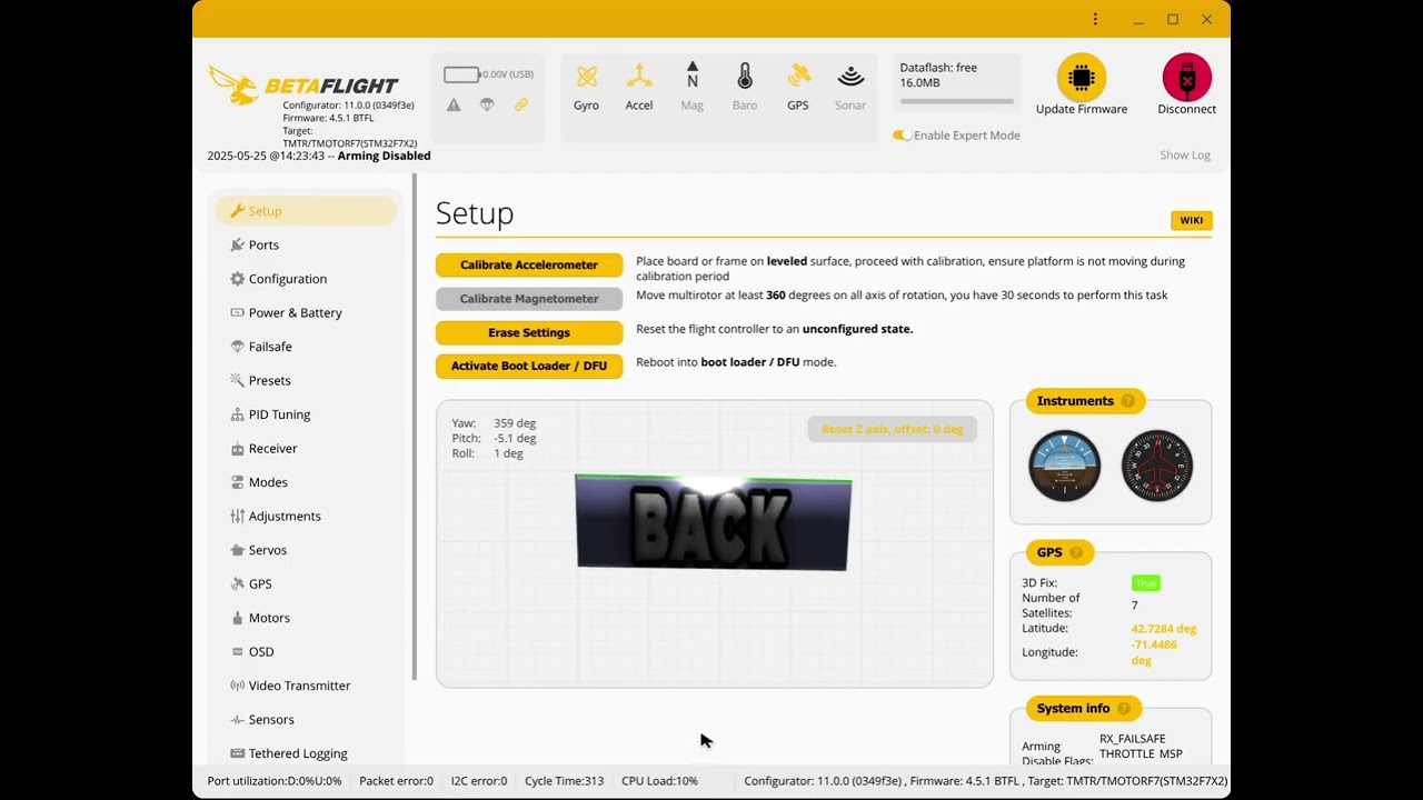
Betaflight does not have a wizard for transmitter setup, and the throttle low limit is the same as other channel's low limit. We manually set all channels' low PWM to 989us even though they can produce 988us PWM because arming code dictates that throttle needs to be lower than the channel's low limit. In LibrePilot wizard, the Collective input value is not isolated when the wizard collects Throttle input value, resulting in a mix-up of the 2 inputs. Our production Converged-AIoT.uav has the fix. It was fixed by manual entering channel numbers after wizard finished its work. The arming dictates that throttle channel needs to be no higher than, neutral level PWM, but low limit needs to be lower than neutral. Librepilot has individual channels' low limits, so, we set low limit to 0 to satisfy the second condition. And we set the neutral to 174 because the throttle output to ESC is scaled from neutral to high. In either case, setting the throttle point closest to actual TX signal's low point gives most precise RPM output.

Betaflight 4.2.5 Aviation Computer HGLRC Forward411 Allows Accidental Disarming Recovery

Avoid Unnecessarily Complicated Disarming Recovery: During the pre-prototype build, the RF controller's arming switch SD (or QX7's equivalent SF) was unnecessarily complicated in the throttle cut mixed into channel 5, as the following 2 graphs.
 

https://archive.org/download/yt-k4Js8A-LcXg/yt-k4Js8A-LcXg.mp4
Channel 5 RPM control bypass means that the aviation computer has no modification on it. So, after a throttle cut, nothing prevents main rotor RPM spoolup if the arming switch is flipped back to high. It is true that a motor mixers of a copter(mmix) require throttle below min_check for arming to be successful and subsequently giving ESC PWM a value anywhere close to 1500us. But our craft doesn't have any motor connected to mmix, instead our main motor is treated as a servo with channel bypass, which takes raw RC throttle input that is not subject to arming manipulation. Further more, collective pitch and cyclic and yaw are a servo mixes, taking RC raw input (source 7) and PIDs outputs, not modified by arming, so, nothing prevents the craft from properly fly and land after an accidental disarm-throttle-cut and uncutting throttle (the upper right cell's condition in the above table). So, the solution is to flip the arm switch back after accidental disarm and land the craft. There is no need for slow spool-up because the on-ground slow-spool-up is meant to prevent blade hitting the ground. Here we are already in the air, away form the ground, and not time for spooling.
However, after uncutting throttle, still disarmed, the stick commands are unpredictable in the air.  Our channel 1 throttle is actually collective pitch that is limited in between -23 and 57 points, PWM 1382-1385us to 1785-1792us. Our min_check=1386 and max_check=1886, so only the 8 red-highlighted commands can possibly be activated with low collective pitch when disarmed. And closer look at the remaining 8 commands shows the changes are inconsequential.
The immediate high throttle without slow spool-up risks servo clutch sprain. And in the test video, the descent is faster than usual due to a sprained, slipped servo clutch lowering the collective pitch.

The prototype and production build don't mix disarming into the throttle cut. Again, Channel 5 RPM control bypass means that after accidental disarming, nothing prevents a stable craft from leveling mode and landing as usual. This avoids risking a sprained, slipped servo clutch.

The craft robot was created by humans, but that doesn't mean it is superior to humans and should judge human errors on the RF transmitter commanding RPM to the rotor while disarming the craft. Mixing the motor cut into the arming switch was about that, and it only complicated things further. 

The reason the production build's Betaflight 4.5.2 can not do this recovery is because 4.5.2 software disables yaw integral I term when disarmed. So, a failed full rearminig means the tail will rotate continuously.


Nonviable substitution Flywoo F745 Nano Aviation Computer

The F745 Flywoo software has a custom bootup behavior, solving the "twitch" problem of generic F411 software. Due to some difficulties, the difference is persistent from version 4.2.0 through version 4.2.5,. The source code of 4.2.5 may show the branching between F411 and F745 of the difficulties.
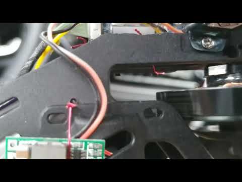
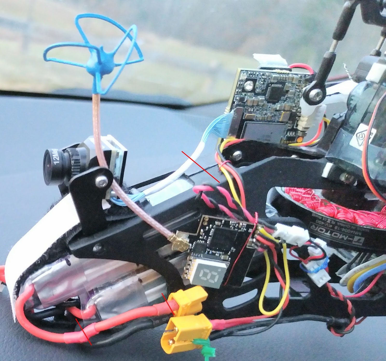
When fixating the wires, avoid anchoring into the crevasses between the components because the stiff wires can easily damage the components, as illustrated in the picture above on the right. Each wire should be anchored by 2 points on the board to prevent ripping the solder pads. The first anchor is the threading through the tight exit holes.  The front wholes are the second anchor for GPS and RF receiver wires. Camera, VTX, Main M1, VBAT-, and S4 wires are glued to a chip flat surface as the second anchor. VBAT+ solder pad is too close to the fixture hole for effective glue anchoring, so its wire uses one extra loop-around on the exit hole as the second anchor. 

As pictured on the right, each board fixture whole is capable of allowing seven 1A (26 AWG) wires through, or five 1A wires plus 3 thin servo signal wires. As pictured above, the F745 does not have the flat surface of JST 1mm socket like that in the F411 board. So the rear mount is 3 layers of the clear mounting tape perforated by the array of signal output, with an extra layer of narrow strips front and aft the array of pins. The front mount has a piece of paper to cushion the barometer hole to prevent air sealing. The rear 3 servo signal points are soldered in-place after the board is mounted.
Use the F745 software version 4.2.5 with this configuration .
The Main M1 signal wire appears inadequately short in the pictures due to the alternative fixating of the wire through the bottom side of the board. It should have been on the top side, and there is a good anchoring area on the OSD chip on the top side. Also this alternative fixating makes eight 1A wires through the fixture hole, which is exceedingly tight and a difficult work.
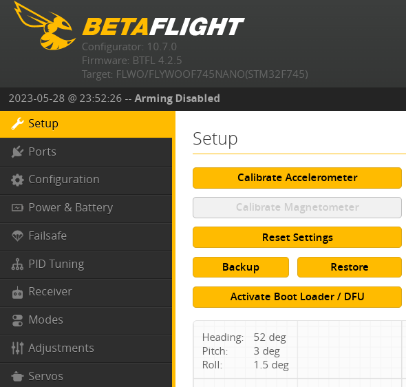
The second behavior difference is the accelerometer startup. 
https://archive.org/download/yt-S8DKwxUguTk/yt-S8DKwxUguTk.mp4

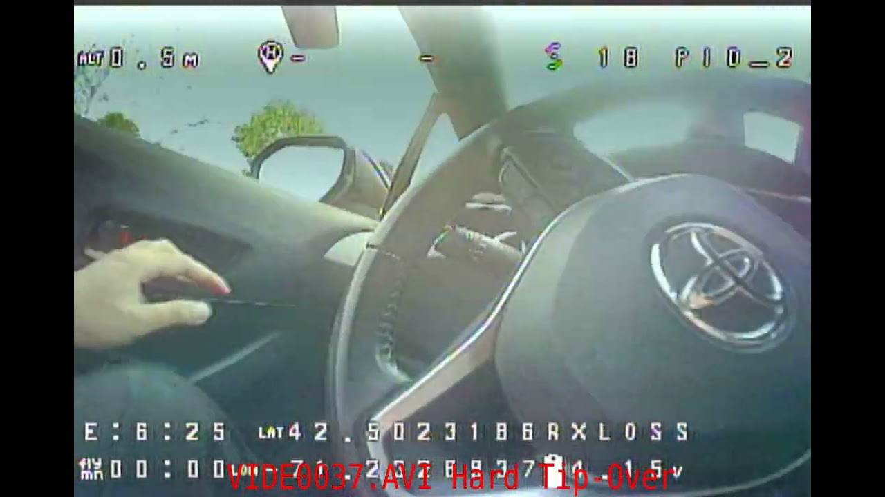
However, even with the Calibrate Accelerometer extra step, the switch-on of the accelerometer during the takeoff procedure can still frequently tip over the craft, 1 out of 5 to 10 tries, as investigated in the video above on the right. The overall difference between F411 and F745 aviation computer configurations is here,
$ diff dump_all_converged_AIoT_hglrc_fd411.txt dump_all_converged_AIoT_flywoo_f7nano.txt
12,14c12,14
< board_name HGLRCF411
< manufacturer_id HGLR
< mcu_id 002000503439510f37393937
---
> board_name FLYWOOF745NANO
> manufacturer_id FLWO
> mcu_id 0044002a3135510731303738
17c17
< # name: HGLRCF411
---
> # name: F7NANO
... hardware pinout differences ommitted here...
270d273
< feature SOFTSERIAL
311,312c314,319
< serial 1 64 115200 57600 0 115200
< serial 30 2048 115200 57600 0 115200
---
> serial 1 64 115200 115200 0 115200
> serial 2 2048 115200 115200 0 115200
> serial 3 0 115200 57600 0 115200
> serial 4 0 115200 57600 0 115200
> serial 5 0 115200 57600 0 115200
> serial 6 0 115200 57600 0 115200
315,318c322,325
< led 0 0,0::C:0
< led 1 0,0::C:0
< led 2 0,0::C:0
< led 3 0,0::C:0
---
> led 0 6,6::CO:8
> led 1 7,6::CO:8
> led 2 8,6::CO:8
> led 3 9,6::CO:8
548c555
< set acc_calibration = 0,0,0,1
---
> set acc_calibration = 0,0,0,0
553,554c560,561
< set mag_bustype = SPI
< set mag_i2c_device = 0
---
> set mag_bustype = I2C
> set mag_i2c_device = 1
557c564
< set mag_hardware = AUTO
---
> set mag_hardware = NONE
560c567
  
< set baro_bustype = SPI
---
> set baro_bustype = I2C
562c569
< set baro_i2c_device = 0
---
> set baro_i2c_device = 1
609c616
< set blackbox_p_ratio = 32
---
> set blackbox_p_ratio = 16
909d915
< set system_hse_mhz = 8
913c919
< set cpu_overclock = 108MHZ
---
> set cpu_overclock = OFF
951c957
< set dashboard_i2c_bus = 0
---
> set dashboard_i2c_bus = 1
964c970
< set flash_spi_bus = 2
---
> set flash_spi_bus = 1
970c976
< set gyro_1_spibus = 1
---
> set gyro_1_spibus = 4
973c979
< set gyro_1_sensor_align = CW0FLIP
---
> set gyro_1_sensor_align = CW270
975,976c981,982
< set gyro_1_align_pitch = 1800
< set gyro_1_align_yaw = 0
---
> set gyro_1_align_pitch = 0
> set gyro_1_align_yaw = 2700
978c984
< set gyro_2_spibus = 1
---
> set gyro_2_spibus = 4
990a997,998
> set i2c4_pullup = OFF
> set i2c4_overclock = ON
1006c1014
< set name = HGLRCF411
---
> set name = F7NANO
  

Nonviable substitution Speedybee F405 Mini 20x20 Aviation Computer

The ICM42688 gyro of the Speedybee F405 Mini requires the Betaflight notch filter to approach, but not match, the stability of BMP2700 and MPU6000 gyro of T-Motor F722 Mini and HGLRC Zeus F722 Mini/HGLRC Forward F411, respectively. The best possible video with Speedybee is here, which has frequent random bumps and twitches.
https://archive.org/download/yt-LprH2nkWQDE/yt-LprH2nkWQDE.mp4


14-Pole EMAX 2808 660KV Motor   

Below first 5 photos are of the same motor. The bell weighs 23.2  grams consistently. The modification to thin wire saves (30.6 + 23.2) -  52.8 = 1g. The 6th photo is of another motor. The stator weighs 52.8-23.2 = 29.6g to 28.7g with thinned lead wires, so 30.6g  to 29.7g with original wires. Worst case with stator trimming 30.6 + 23.2 = 53.8  grams.

   
The 2808 motor stater trimming needs a combination of drills and pre-cuts in contrast to 4004 motors that only need pre-cuts. The outer ring does not need rotary cuts; the pliers bend and pull out the ring sections individually. Trimming the 2808 motor stater saves 33.2 g+0.1 g - 30.6g = 2.7 grams. The trimming of the 2808 motor stator base is mandatory so that the anti-rotation zip tie can thread through beneath the base. So, overall, this alternative motor weighs between 52.8 and 53.8 grams. Looking back at the first picture of this discussion section, Carving out the excess base, trimming out excess wires, and removing the stock shaft save 2.7 + 1.7 + 2.4 = 6.8 grams, resulting in 60.6 - 6.8 = 53.8 grams. The excess wires weigh 1.7 grams. 
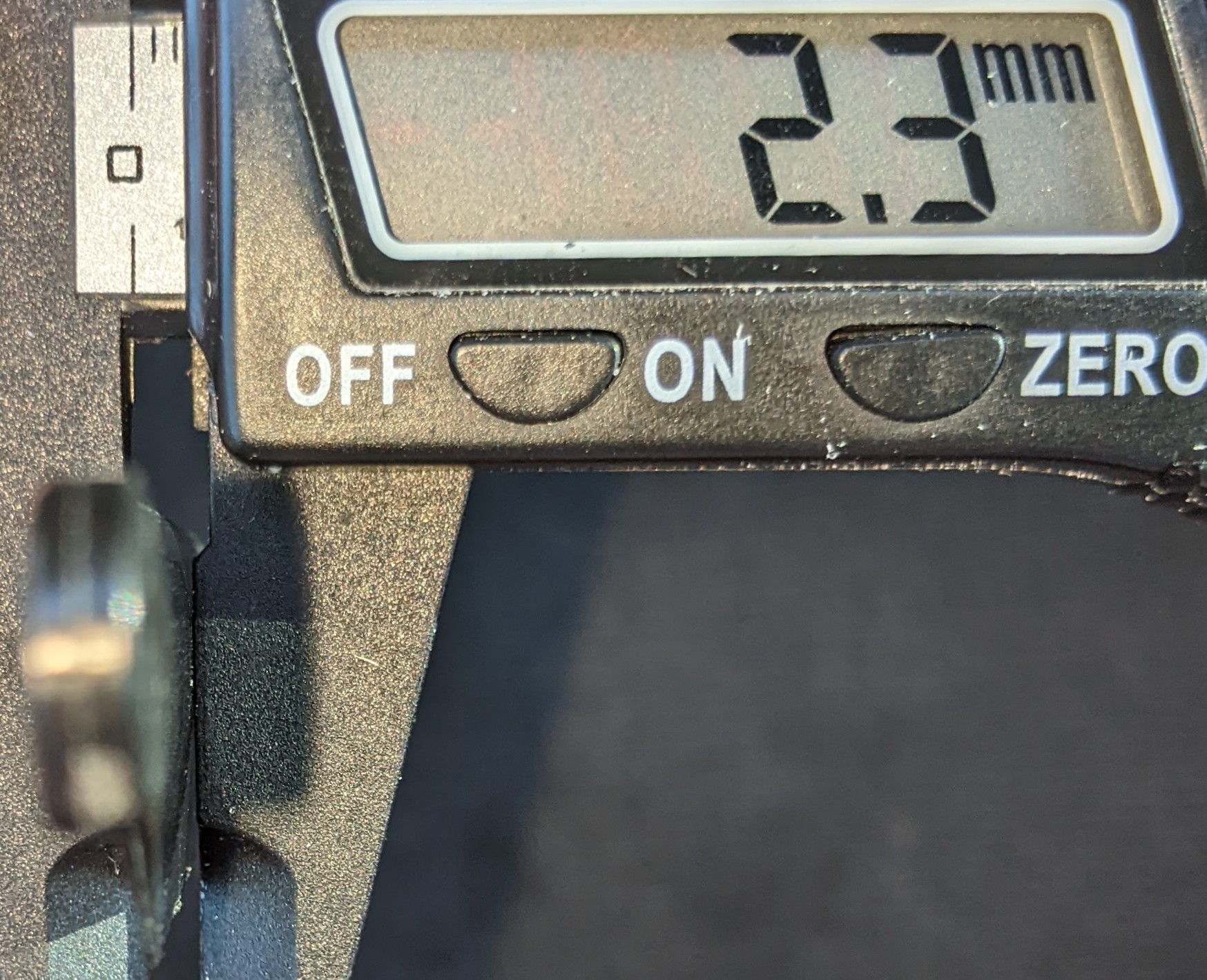
When clamping the shaft down the second time with the push rod assembly, use a 3/8-inch wrench socket with the 2808 motor, as shown below. The 4004 motor and 2808 motor are interchangeable, providing that the 2808 motor has a 0.5mm shaft protrusion at the bottom of the motor, as opposed to the 4004 motor's 2.8mm protrusion The difference of 2.8-0.5=2.3 mm, matching the motor height difference of 21.3-19=2.3 mm.

https://archive.org/download/yt-HrvFCTlth3U/yt-HrvFCTlth3U.mp4
To understand 
tuning RPM in BLHeli Configurator for the 14-pole 2808 motor, consider increasing RPM by 50 from 2643 to 2693; the new scaling size 981, which produces 50000.0 / 7.0 * 74.0 / 200.0 * 1000.0 / 981.4 = 2693 RPM. So, a 19 PWM change produces a 50 RPM change, a 1 to 2.5 ratio. Also, with the small diameter of the 2808 motor with smaller torque, the fail-safe test video on the right successfully recovered RF control loss with a 2808 motor using ESC governor p-gain 0.5, the same value as the 4004 motor's high punching power setup.   


Main motor ESC 


Align300x Main Grips - 8.5g

They have the same arm span of 12mm as the Align250Pro's grips. They have the same radial bearing spacing and depth as Align250's. But they are longer and can accommodate a thrust bearing at the far side. Unless trimming the main blades, Align250's grip span is too short to accommodate any thrust bearing in-between or at the far side. 

The Align300x grips need to be paired with Align300x's hub because the feathering shaft's width is limited to 38.5mm in the market. Overall, this alternative adds a weight of (8.5+2.45-0.3)-(6.2+1.4)=3 grams.
 

Walksnail Pro Camera

Remove the casing saves 11.271g. Don't use the camera itself that is (5.646+0.981+1.336) = 7.963g. 15.668 - 7.963 + 0.608 = 8.3g. 


Spool-up collective pitch angle can be tuned to a smaller angle 

But, wait, during spoolup, the aviation mode is manual, the tail motor does not spin, so some negative collective, say -15 points, is required to produce friction between landing skid and the ground to prevent tail spinning. Remember, zero collective pitch doesn't mean zero torque. 
Also, if you tune it to very close to 0 points (0 degrees), say -1 point, Betaflight min_check=1386 configuration needs to be raised to min_check=1500 , so that the craft can arm. Remember, whenever RF transmitter is turned on, the -23 points, or, the new -1 point, is activated. And you need to arm the craft at this -23 points or -1 points that is lower than min_check . However, if you actually set min_check to 1500, any slight touch of ANY stick toward low position triggers the stick command(s) as the first picture below because min_check applies to all sticks.
One possible solution for allowing near-zero-collective-pitch-spoolup is to enable computer stabilization during spoolup and disable stick functions all together. But disabling stick functions requires modifying source code of betaflight, and enabling computer stabilization on the ground defeats the purpose of the spoolup-manual mode. Another possibility is to set up the throttle channel 1 as the main motor PWM RF signal, but the aviation stabilization features that are based on throttle channel 1's variation, such as "TPA" and "TPS", can not be used because the helicopter's main rotor RPM is a constant during the mission. 
From safety stand point of view, the negative spoolup pitch should be as far from the stick center as possible; from the operation stand point of view, the stick should be as close to the neutral collective pitch as possible.
The only viable possibility is to physically dial up the servo clutch so that PWM 1385 is the neutral position with zero collective pitch. And such alternative needs the collective pitch curve shifted down as above second and third pictures, but still the near-zero-collective-pitch-spoolup's tail spinning problem is not solved.

It is possible to automatically disengage pilot's RPM spoolup

We can use a logical switch in the RF controller to automatically switch on the accelerameter(attitude) mode as soon as the throttle goes higher than -26 (74 out of the 200 points) of 1/4 throttle stick position. But this means that accelerameter(attitude) mode can be downgraded to manual spoolup mode during mission when throttle stick is lower than the 1/4 position. This is due to the fact that logical switches don't have direction awareness whether a craft is taking off or landing. So, pilot would end up needing to be trained to avoid lowering stick to lower than 1/4 position when the craft is in the air in attitude mode in this alternative setup, which can be difficult. One possibility is to use a manual mode throttle curve that reaches spoolup at 1/8 stick. But, still, pilots needs the extra training to avoid lowering stick to 1/8 position. And, the 1/8 position spoolup makes the stick very sensitive to the touch during spoolup. 

It is possible to tune the spool-up sensitivity

The 1/4 position full spool up can be changed to 1/8 position with the 9-point throttle curve, which the rotor RPM becomes very touchy and sensitive. 

False Alternative Kalman Filter

Neither HGLRC FD411 nor CC3D has the main development branch with Kalman filter. Frequency domain engineering is still the mainstay in the foreseeable future. This is a false alternative.

Five Alternative Battery Packs

650mAh is an alternative that needs alteration of the main frame, trimming out the battery bay ceiling beam, which severely weakens the crash resistance and is unsuitable for adrenaline proximity diving. The crazepony 2S batteries are lighter, 2 packs joined by the trimmed powering wires, not the charging wires.
The GNB packs are heavier and 1mm taller. And the lower jaw of the battery cage needs to be ground 45 degrees at the opening. When the back is installed into the battery compartment, the upper pack is stopped at the wall stud inside the main frame. The pack build uses 18cm of clear tape. The GNB 4S 650mAH, pictured below, does not need the grinding of the main frame.

The RDQ 525mAH, pictured on the right, has the same dimensions as GNB 520mAH but is 0.4 grams heavier.


 The XT30 connector can be substituted with EC2 connectors

 without adding weight, but EC2 needs clamping tools. 


For the FrSky XM Plus receiver with a repairing replacement antenna, 

the replacement is about 1 inch longer and it coils around the boom stick for 1 turn. 


High-wind FPV landing is risky. 

https://archive.org/download/yt-L_JZBcEhoOI/yt-L_JZBcEhoOI.mp4
In the above landing approach, I first tilted the head of the craft down so that I could see obstacles around the landing patch on the ground. I continued to keep the head down so that the camera points toward the ground from 0:12 to 0:22 while descending. I ended up facing wind and away from the landing patch because the wind is blowing toward the fence. I flew blindly because I was facing away from the fence and landing patch from 0:22 to 0:30 during final approach. I ripped off the FPV goggles at 0:32 to try to land line-of-sight, but I didn't have the training to fly LOS when the craft flies toward me at the landing target. I was disoriented at 0:37. It crashed.
The appropriate approach planning should be exercised to reduce the risk of landing in high wind as the following table.
This is the most favorable condition. Same with landing an airplane. The head wind slows down the craft. The craft elevator tilts downward to resist the wind. At the same time, the FPV camera points toward the ground for clear view of obstacles.


With crosswind, unlike an airplane, the drone does not need to change approach heading because the drone flies side ways just as fast as flying forward. So, the craft tilts side ways and forward at the same time  FPV camera points toward the ground for clear view of obstacles.

With tailwind, without changing approach heading, the craft needs to tilt its head up, pointing FPV camera toward the sky resulting in blind landing. If the pilot heads toward the wind to tilt the FPV camera down to see the ground, he is facing away from the landing patch flying backward blindly as seen in previous crash landing video. The solution is to change heading and convert the tailwind to cross wind. The field of view of the camera only approaches 180 degrees and less, so the side way approach needs a slight forward movement, and the craft lands slightly off the landing target.

With tailwind and slight crosswind, the heading should be perpendicular to the wind and heading toward the crosswind component of the wind. The landing target is with in the field of view of the camera. The craft tilts toward the ground to resist the crosswind at the same time the FPV camera points toward the ground for clear view of obstacles.


When crosswind mixed with headwind, no heading changes needed because there is no tailwind component to force the pilot to tilt the craft and the FPV camera toward the sky. This is the first and second condition combined. And not heading change needed for either component of the wind.


Terminal Speed Diving And Punch-Out With 3-Series LiPo Battery


On punch-out, with pre-prototype build of 3S battery and diving at RPM 2607, punch-out with maximum 1666us PWM on ESC and full pitch, airfoil operates as the following diagram.
The 34 degree effective collective pitch has extremely high drag results in collapsed RPM. The airfoil operating point moves towards the wrong corner of the lift curve never to recover the RPM. Crash experiments below with 2 incidences, the first dive starts at 1:00 mark.  In either case, full throttle is applied at the same time of leveling the craft by virtue of high-velocity pitch-up mechanism.

https://archive.org/download/yt-AP6Rui1JB-k/yt-AP6Rui1JB-k.mp4


A workaround for the weak power plant is to maintain the diving collective pitch for a few seconds,  after angling the craft for punch-out. as the following airfoil operation diagram.

In such a self-imposed aviation-envelope, at 23 degrees effective angle of attack, the lift slows down the descent enough that the airfoil operating moves to the normal operation region, as the following video, which holds back throttle for 3 seconds at the bottom of the dive after leveling the craft to horizontal. This dive still used RPM 2607.
https://archive.org/download/yt-7X1T3yMSLt4/yt-7X1T3yMSLt4.mp4

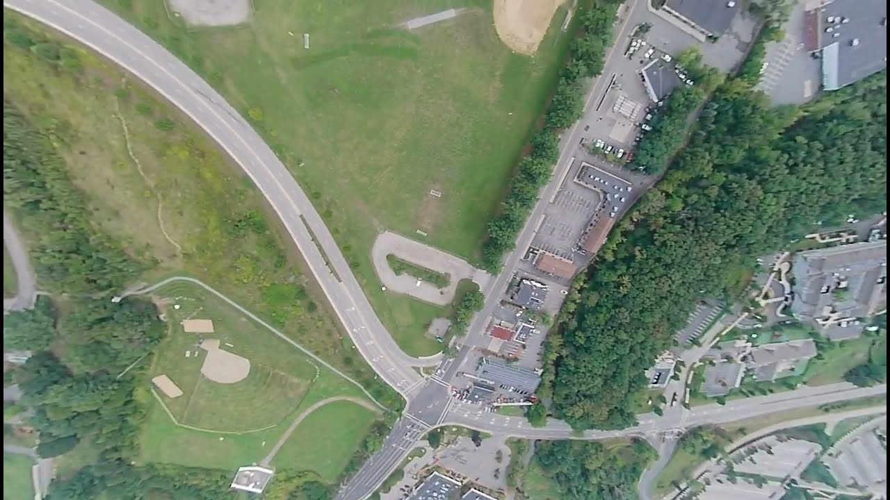
And with RPM 2607, I can only eliminate the swinging motion by diving with 20 degrees off the vertical line. Terminal vertical speed is 20m/s, as seen in urban diving video, which is significant to the rotor head wind speed, at 42%, 20 to 48 m/s that is calculated in build notes.


AKK IPEX 5.8GHz antenna - 1.2 grams            Oxy2 Sport DFC Bolt Set - 1.2 grams


Dampener

The Rakonkeli CNC delrin dampener is compatible with the 180CFG hub.


HD-FPV Camera

Four different powering options have been tested, similar to the FPV camera setup section of the high-performance build post https://nocomputerbutphone.blogspot.com/2018/08/converged-drone-at-edge-of-space.html.
  1. The MP1584 chip-based buck converters, such as the Bluesky 5V power supply, are the worst for analog video applications.
  2. The second worst noise interfering with FPV feed is with 12-16V direct battery power supply to the Caddx Turtle cameras (v1, v2, and Baby) in the following video; if you watch the original feed video file https://drive.google.com/file/d/1nL07CPVMDrWu_w7SFtraSYZqxUejrDJr (download it then watch it on a video player instead of watching it online with an online player because online video servers process out the noises to save their internet bandwidth).
  3. The FPV feed is best clear of interference lines when VTX's 5V aux power filters out low-frequency ripples. However, the market trends move away from VTX aux power and toward pass-thru powering.
  4. The solution is to share power with servos of the base build, the same as the high-performance build, which has a Wolfwhoop MP2315-chip-based buck converter power supply. 
With an extra alternative 10uH inductor, the FPV feed has the video ripple noise level between direct battery power and VTX's aux power in this solution. The ripple noise can not be completely eliminated with a 10uH inductor LC filter because the ripple frequency is similar to or lower than the 10uH inductor working frequency. The ripple noise can not be eliminated with an electrolyte audio A/C capacitor, either, because the ripple frequency, around 1MHz, is much higher than the electrolyte capacitor's audio working frequency. 
As pictured on the right, a scrap plastic strut fixture is needed to hold the camera board vertically. Use kevlar strings or enameled wires to tie the board to the strut and craft body. And then, CA glues the fixture arm.
Prepare the SD card by sticking it onto a tape with a mounting square, then tear off half of the unused tape. After installing the SD card, fasten the mounting square onto the steel plate of the camera board.
Do not drill holes on the sides of the main frame wall to fasten the camera board because that will weaken the structure and damage the camera wire connectors during a crash.  The experiment shows a complete cleavage of the upper main frame when the left side wall is weakened with fastening holes. 
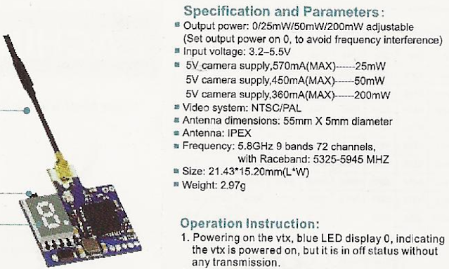
The alternative Eachine VTX03 has AUX power at 360mA, as shown in the specification on the right. It can give the best FPV feed with Caddx Baby Turtle. However, as seen in the following specification comparison, the alternative Runcam Split has a much larger power consumption than the VTX03 can support.
Runcam Split series tapping AUX power of VTX03 results in video freeze with high G maneuver power surges/dips. One incidence of such video freeze is below on the left during punching, where the drone is lost from a considerable altitude.
https://archive.org/download/yt-tTL2aIsu9CI/yt-tTL2aIsu9CI.mp4
https://archive.org/download/yt-x_5svuNhQqA/yt-x_5svuNhQqA.mp4
A second video freeze incident with Split is above the right. If you watch the video to the end, the frozen last frame stays indefinitely after the drone touches the ground.


Substitute T-Motor F722 Mini (US stock fast shipping)

Half and half of all diving videos on the extreme robotics page are with HGLRC Zeus F722 Mini and with T-Motor F722 Mini. The T-Motor aviation computer is 1.4 grams heavier; the Skystar aviation computer is 0.8 grams heavier than the T-Motor aviation computer, still.


When using the T-Motor F722 mini aviation computer, the servo power tapping and the battery power input switch sides from the production build. This is because the signal bus of the aviation computer is in the mirror orientation between the T-Motor F722 and HGLRC F722, as the following picture shows. This substitute aviation computer is used in many videos in this page.


dumpall https://drive.google.com/file/d/1JKzeFYqmqPGFbU8UPpW67yoY2VoHuNzC/view?usp=drive_link

When using this substitute for scientific investigation purposes, the dump_all file differs from the production build in PID sampling rate, gyro logging rate, gyro data filtering mechanism, and GPS algorithm, as follows,


test@penguin:/mnt/chromeos/MyFiles$ diff dump_all_converged_AIoT_HGLRCF722.txt dump_all_converged_AIoT_TMOTORF7.txt
# pinout/timer/dma/servo center/ truncated
510c504
< set gyro_lpf1_static_hz = 0
---
> set gyro_lpf1_static_hz = 125
512c506
< set gyro_lpf2_static_hz = 188
---
> set gyro_lpf2_static_hz = 0
529c523
< set gyro_lpf1_dyn_max_hz = 0
---
> set gyro_lpf1_dyn_max_hz = 500
574c568
< set blackbox_sample_rate = 1/2
---
> set blackbox_sample_rate = 1/4
# barometer/board/gyro orientation/ibata truncated
672c666
< set gps_ublox_flight_model = AIRBORNE_1G
---
> set gps_ublox_flight_model = AIRBORNE_4G
710c704
< set pid_process_denom = 8
---
> set pid_process_denom = 1
714,715c708,709
< set simplified_gyro_filter = OFF
< set simplified_gyro_filter_multiplier = 100
---
> set simplified_gyro_filter = ON
> set simplified_gyro_filter_multiplier = 50
# camera control/pinio truncated
test@penguin:/mnt/chromeos/MyFiles$ 

There is no difference between using lpf1 (my t-motor f722 setup) and lpf2 (my zeus f722 setup). Lpf2 filters before PID loop sampling the craft attitude; lpf1 filters after PID loop sampling, which is a Betaflight software design error. But the advantage of lpf2 is only to quash the aliasing noise frequency at the difference between gyro data sample frequency PID loop frequency. Here the t-motor f722 has no difference between the 2 frequencies - both are  8kHz.
The blackbox_sample_rate of 500 Hz in the production build is sufficient for generating fingerprints for Gyroflow to lock time-matching points.

A test with 125 Hz could not reliably make lockings of time matches. Gyroflow-smoothered video with a 500 Hz logging rate is in many videos of this page.

With the GPS connected to the same power source as the RF control receiver, the GPS power wires are twisted onto the receiver power wires. 
https://archive.org/download/yt-MCCyOFvMd1s/yt-MCCyOFvMd1s.mp4
This allows GPS to be locked before powering on the craft with the battery. It is suspected to add interference to the gyro with the added active GPS electronics in the first few seconds of booting up the aviation computer, which is the time when the gyro is calibrated by software. However, the test video on the right shows no more yaw drift than the production build's GPS powering scheme.


NACA(NASA) 0015 And 0012 Airfoil Both Capabile Of Terminal Velocity Diving Punch-Out

The airfoil of SP-Oxy2-081 (black graphite nylon) blades and SP-Oxy2-086 (colorful nylon) are NACA 0012 and 0015 airfoils respectively. Search "SP-OXY2-086" or "SP-OXY2-080" is most effective in finding sellers.

NACA 0012 airfoil stalls at 2 degrees earlier in attack angle as ploted here (50,000 Reynold's Number, between aqua color ncrit number 5 and soil color nrit 9). 

https://archive.org/download/yt-AGrCzEFi1LU/yt-AGrCzEFi1LU.mp4
When punching out of a terminal velocity dive, the collective pitch needs to be delayed. Do not add a collective pitch first because helicopter physics dictates that the craft pitches upward with a positive collective pitch, resulting in stalled movement with a large collective pitch in a high sinking rate. The video on the right (with Sunnysky v2806 400kv motor and 20A ESC) shows the stalled, stumbled punch-out when collective pitch was applied too soon and forceful. The NACA 0012 airfoil punch-out requires more skillful, earlier, subtler cyclic pitch-up to keep the craft borderline stalled while the stall lowers the craft; video footage below on the left. The NACA 0015 airfoil punch-out does not encounter stall by procedure; video footage below on the right.
https://archive.org/download/yt-Imbz30RExJA/yt-Imbz30RExJA.mp4

4-series lipo is required in this procedure. The 3-series Lipo battery punch-out has a different procedure to avoid vortex ring state, discussed in the substitute parts chapter page, not on this page.

Upscaling To 4K For YouTube

The 2 videos are for comparison between uploading 1080p and 4k of the same video. If you watch them both at 720p, you will notice the difference when the craft is near the ground. The 1080p uploaded video has polygon blocks of blurs; the 4k uploaded video is closer to original video.
https://archive.org/download/yt-xm8Z4y2BV_I/yt-xm8Z4y2BV_I.mp4
 
https://archive.org/download/yt-Nie4DoG2hCM/yt-Nie4DoG2hCM.mp4

A one-minute 1080p video with H.264 encoding is about 400 MB. The above footage is 40 seconds long. Upscaling to 4k makes a file 250% as big. H.265 encoding makes a file 60% of the upscaled file size, about 400 MB as the end result. Both were 60 FPS.

540p uploading can not improve the polygon blurring, even though it reduces file sizes to 60% of the originals, as shown in the file listing below. The last four entries in the file listing below show that Gyroflow output at 720p can not reduce file sizes; the 30fps file at the bottom fifth listing has file sizes reduced by 25%, not 50%, at the expense of a very choppy viewing experience; Gyroflow produced 100% smooth videos that are more choppy in actual viewing, with only 10% file size reduction in the fourth and fifth listings. The AvatarS0162 and AvatarS0163 are nearly exactly 1 minute each.
.

Substitute Carbon Fiber Fuselage Has Nearly Identical Weight


T-Motor Shaft Work Surface  Finishing

When using T- motor, regardless of the shaft used, the bell rim only needs scraping once, as pictured on the right, because there is no slope of the bore opening like what the Sunnysky motors have. 

Vertical Battery Substitute

The Velcro on the battery should only have a slip opening to allow the front wiring to go through. No need to crop the Velcro as the hole only allows the material to stretch and distort.


?

The underside of the craft's protruding Velcro strip needs a backing of another hook Velcro strip to mount the battery. 


Substitute Video Antenna Stiff Tubing

The tubing of the Runcam Link antenna is of a stiff and brittle material. It is too long and can easily damage the coaxial cable. To remove a section of the tubing, use a rotary cutter to score (not cut through) the tubing material into 3 sections and give the middle section longitudinal scoring on 180 degrees opposite sides.

Once scored, the 3 seconds can be separated by hand, and the middle section can be crushed and split by pliers gripping at an off angle from 180 degrees.

Some sales of the 9cm video bus cable include a plate that needs to be removed. The plate is of molded metal and can be cracked with pliers (no rotary cutting needed). The video computer board uses 3 ziptie mount points. The lower aft ziptie needs pre-bending.
 
Plastic housing borehole of Walksnail Avatar 1S is only drilled diagonally from the factory. Drill the missing upper left hole with a 1.1 mm bit, so that a Kevlar string can be tied to fasten the camera onto the zip tie. 

Use Skystar Mini F4 Aviation Computer For Single Solder Scheme


Thrust Bearing Complicates Building 

The good dives are reproducible consistently using Oxy2 grips, which have thrust bearings pictured here. 
When installing the Oxy2 grips, watch out for factory assembly mistakes that occur about once every 10 pieces by the tentative(without washers and without hard cranking) installation of the feathering shaft and pulling, as shown in the following video on the. But, first use a marker to mark a dot to make sure, if the pulled grip rotates smoothly by itself or by rotating the shaft and the other grip's bearing provides the smoothness. A correctly assembled grip set should feel surprisingly and pleasantly slick in the pulling test on both grips.
 
https://archive.org/download/yt-TO3bzg03NIM/yt-TO3bzg03NIM.mp4

The technique in the following left-side video is incorrect because a good grip on one side can ensure a smooth rotation on the other side, masking the problem of one-sided manufacturing mistakes. The following right-side video shows the entire assembly process.

https://archive.org/download/yt-EQuRBeqVZZM/yt-EQuRBeqVZZM.mp4
 
https://archive.org/download/yt-Oh5kgV_iiyk/yt-Oh5kgV_iiyk.mp4
 
The factory assembly sometimes misplaces a high-error inner thrust disk instead of the low-tolerance outer thrust disk, as explained in the video above on the right. Discard the bad grip. The outer thrust disk needs to hug the feather shaft tightly because the radial bearing's inner tube needs to rest on the outer thrust disk without sinking into the crevice between the shaft and the disk, which would result in transferring centripetal, axial force onto the junction between the outer radial bearing's inner and outer tube. The general AIoT kit build uses Align250 main grips without thrust bearings to avoid the added build complexity.

Chromebook Dual Boot Xubuntu

A dual-boot Xubuntu installation on the Chromebook's internal disk partition "STATEFUL" that runs the configurator stand-alone well is documented on the American Way Of Computing blog. The AMD64 binary is downloaded from https://github.com/blheli-configurator/blheli-configurator/releases.

Bare-metal Xubuntu Gyroflow GPU renders HD footage 30% faster than the extreme robotics build, as shown in the following picture.
Also, as shown in the picture, the dual-boot Xubuntu only needs to manually install 1 package, Qt6, unlike the Chromebook Linux, which requires manually installing 5 packages.

CPU rendering is often cited as producing higher-quality results. In a real-world side-by-side comparison here, there is no perceivable difference.

https://archive.org/download/yt-3jGRdt__Zzc/yt-3jGRdt__Zzc.mp4
https://archive.org/download/yt-u6ytM3O0Uus/yt-u6ytM3O0Uus.mp4