
AIoT Use Yolo Model With Non-yielding Process


pi@raspberrypi:~$ cat .bash_profile
sh /home/pi/stream.sh
pi@raspberrypi:~$ cat /home/pi/stream.sh


.

Avionics Computer With Stabilization Precedence In Air: The Only Solution

To solve the problems of the previous two paragraphs together, we configure the avionics computer to give the pass-thru mode a channel switch, and this channel switch for the pass-thru mode is tied to a constant negative collective pitch. The negative pitch prevents a takeoff while the pilot spools up the rotor with the CV1 curve. In blue bars, we highlight the disabling of the accelerometer and/or gyro sensors. The flesh color underneath all aviation modes is for the same set of PID coefficients throughout all modes.
When the first mode does not set the collective pitch to -23(that prevents liftoff) via an extra channel one mixer page in a faulty improvised setting, the pilot may forget to switch channel six to the middle position when attempting to reduce time to takeoff to save battery life in the midst of enabling video recordings and operating other equipment. The result is forceful crashes due to the high power applied for takeoff and the high-speed drift of the manual mode. The video of such a crash is on the right.
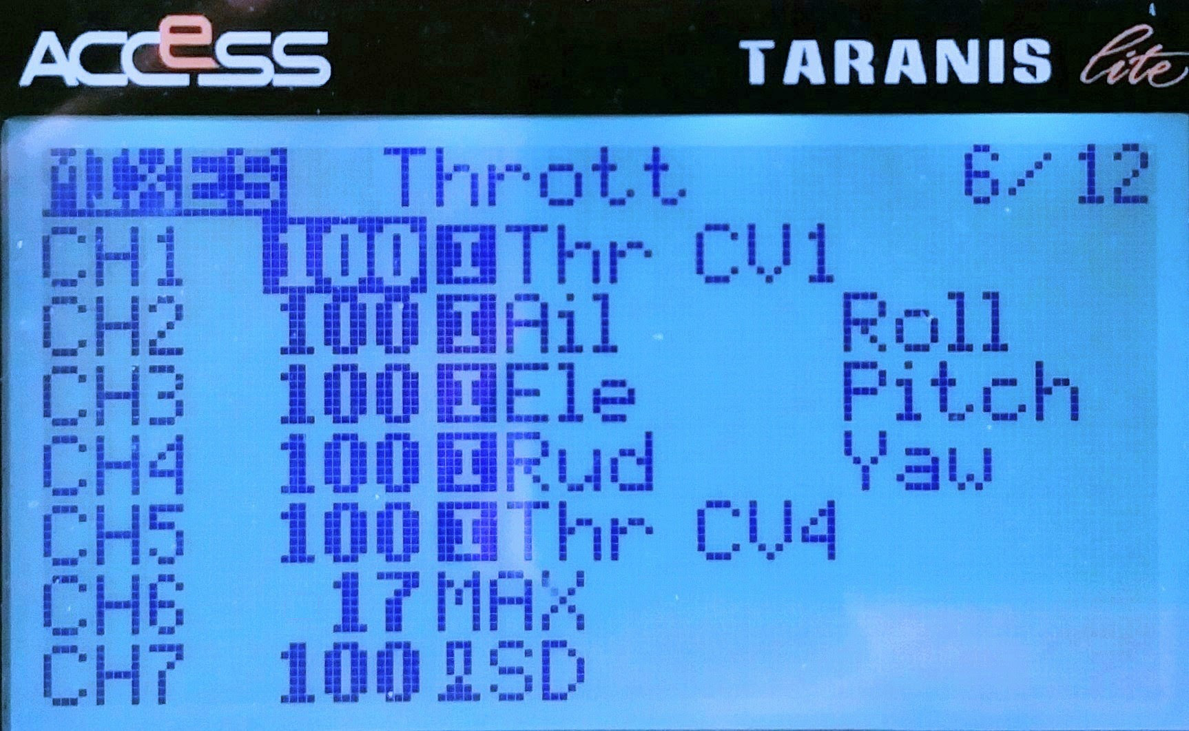
When the transmitter and avionics computer setups are improvised out of sync, the takeoff can happen in gyro-only mode. This happens even after a hand-tethered hovering test because the gyro-only mode hovering can be successful without the pilot knowing that the modes are out of sync, for that gyro-only mode does have stabilization characteristics. Then the actual takeoff will, again, crash badly due to the high craft momentum nature of the gyro-only mode. The video of this gyro-only mode takeoff is on the right. This field fault occurs when we are tempted into setting a single 2-position switch on Aux2-channel6 for a cruise-only mission. In the field, the PWM for profile switching appears to need more than 33%, say 40% or 50%, weight to expand over the 1/3 spool-up region at a low position. And that is true for a 2-position switch, but Betaflight would interpret the high position (2000-1500)*0.4+1500=1700 in the gyro-only setting because the weight scaling is centered at 1500, not 1000, as depicted in the diagram on the right.


Motors: Use Multi-Rotor ESC Software For Fast Response
| Endurance prototype | Racing prototype | Converged production | |
| Main motor size | 4004 | 4004 | 2806 |
| Main motor RPM | 2640 | 3100 | 3250 or 3430 |
| Main rotor diameter | 18.6 in/472mm | 18.6 in/472mm | 16.1in/410mm |
| Li-ion Battery | 3 or 4 in series | 3 or 4 in series | 4 in series |
| Main motor software | MAIN | MAIN | MULTI |
| Tail motor software | TAIL | TAIL | MULTI |
| Main motor governor | Compensation with collective pitch | Compensation with collective pitch | BLHeli governor or Betaflight Vbat compen. |
| Avionics software | CC3D | CC3D | BF4.5.2 |
The endurance optimization chapter optimized the prototype power plant for racing with a 2806 motor with a 4-series (13.6+ volts) battery and 180 mm blades. According to airfoiltools.com data of the Joukowsky airfoil that has motor heating inline with the prototype NACA0015 blades, the production build uses the optimized setup. The motor heating at an extraneous collective pitch is just as good as the prototype power plant.
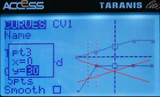 In prototype builds, it was not obvious whether fixed RPM will be required during takeoff and landing. The CV1 spool-up throttle curve picture on the right is super-imposed by collective pitch curve, and the 2 curves were simultaneously in effective with build test hovering. The test showed that the region between the 2 red dash lines had tail punches (yaw turn to the right), indicating insufficient RPM brought on by variable RPM configuration. So, the production build is determined to require fixed-RPM with ESC governor for both takoff and landing, not with the spool-up throttle curve.
 The question was which software among MAIN, MULTI, and TAIL to use with variable RPM in-air. And, MAIN code with the RPM governor disabled, resulted in a RPM change delay of roughly 3 seconds whenever throttle-up and resistance were detected. That meant when the protype craft descends too fast approaching an obstacle, I couldn't punch up the craft immediately because the ESC senses blade foil drags with throttle-up and gives small increments of torque over 3 seconds to prevent damage to the helicopter pinion/gear. There is no resistance reduction gearing in the gearless helicopter setup of our converged AIoT kit, so the ESC needs to apply the torque regardless of resistance, just like a multi-rotor system. The answer is shown in the BLHeli ESC assembly code, which indicates that the MULTI code is simpler/cleaner, without torque detection, and should be used in our AIoT production build.
 The assembly code shows that MULTI code has all the MAIN code functionalities, including fixed-RPM governor, without the unwanted spool-up torque detection, and that MULTI code has all TAIL code functionalities except the unneeded idle spin, and hence the MULTI code should be used for both the primary and tail rotor of converged AIoT builds.
 To configure the ESC, we use the generic F722 Betaflight 4.2.5's passthrough USB-to-UART connection program with BLHeli Configurator Chrome WebApp. Betaflight versions newer than 4.2.5 often have bugs in the PWM protocol ESC passthrough, and version 4.5 completely removes the passthrough. Betaflight 4.2.5 binary hex file for the F722 CPU based avionics computer boards is betaflight_4.2.5_STM32F7X2.hex, downloadable here.
%20(1).png)
For the pass-thru program to work, the MOTOR 1 pin needs to be temporarily assigned to the SERVO pin of the tail motor(SERVO 4 in CLI), while the 4.2.5 software is not supported by the latest Betaflight configurator GUI. This means loading the dump_all config file into the CLI terminal (which is supported despite the GUI being unsupported) to do the "resource" reassignment commands and the "save" command. This also means forcefully running a "save" command after loading the dump_all config because there are command features of the version 4.5.2 software that are not supported by 4.2.5, and multiple errors occur during the loading of dump_all. In the above screenshot, the Betaflight software version is reloaded for configuring the ESC properly, but the resource reassignment is wrong, servo 5 instead of servo 4, and the result is the failure in flashing the ESC software, screenshot here. This means that the signal wire needs to be resoldered when flashing ESC software to the servo 4 lead.
 Safety precaution dictates that motor power with ESC battery should be applied last after all connections and software are set up, and motor power should be the first to be torn down after any configuration/software flashing. With that in mind, power only the avionics computer by connecting a micro USB cable, start the BLHeli app, and click "Connect" with the default baud rate and auto-detected tty port. The computer now reboots into the USB-to-UART adapter program. But, wait, there is sometimes a 1-minute delay for the reboot to occur if the BLHeli program determines that the Internet connection is available but the software website is unreachable, so the best is to ensure Internet access of the laptop PC. Now connect ESC's craft battery power, then click "Read Settings" to connect to the ESC computer. If the "Read Settings" button is unavailable, it is still in the 1-minute period. After flashing ESC with motor software, remove ESC's craft battery power plug first as a safety precaution. Then tear down software/other connections. If you don't tear away the power, when the program switches back to Betaflight software, the motors will spin up to compensate for craft orientation or to match any unintended RF transmitter command signal, posing a great danger. The prototype "compensation" throttle setting for a specific motor, case-by case, is not applicable for large-scale deployment with varying hardware. The solution is to use ESC's RPM control PID governor or (future) avionics computer automatic Vbat compensation. I-Gain needs to be high at 3.00 to track RPM precisely. P-Gain at 0.5, to prevent motor governor oscillation. The governor in the MULTI software doesn't detect torque and has a much shorter acting time than 3 seconds. The entire configuration is as screenshot here.
 The latest, and last BLHeli version is v14.9, and the correct main motor RPM control gains (P=0.5, I=3), startup power (1.25), and damped off were determined during the endurance optimization building to reduce heating and prevent RPM collapse.

.png)
.png)

.png)
 Calibration, configurator needs tentative(first click Live mode and don't click Save in the GUI) Servo 6's MIN set to the high position of 2000. The tail ESC is "Servo 5" in the GUI.
 The tentative MIN position only takes effect after you click Enter or click on a different field in the GUI as shown in the screenshots above. The scaling is finalized when setting back to 1000 to save the calibration.
| The configuration for racing for the tail ESC is the rightful solution for the converged AIoT, shown in the following screenshot and video. Damped off as required to prevent ESC overheating in summer, and is the only tested and documented setting. |  |
Collective Pitch Curve For Fuel Economy


 For simplicity of collective pitch angle calculation, we choose servo arm length identical to blade pitch lever length, in the prototype build, 12 mm pictured above and on the right. The Oxy2 Sport grips and the Align 250 grips have congruent geometry as shown in the picture above. When all 3 pillars of the swash plate are raised evenly, the blade lever and angle are congruent to the servo arm and angle. The angle of travel of the RF control PWM 1000-2000 µs is 83 degrees in the above picture and 84.6 degrees in another test with the avionics computer PWM 1000-2000 µs, averaging 83.8 degrees.


Swashplate Setting
.jpg)
For swashplate leveling, our spool-up is performed in manual mode. If the swash banks to one side of the craft, there is no PID correction by the computer and no heavy battery or long tail lever on the sides of the fuselage to counter the tipping. Use a zip tie with the half-cut end, as shown in the below picture, to check that all 3 pillars nearly touch the servo linkage. This zip tie should only be used after checking for enough room between the swash and the hub after booting up the avionics computer.
 It is well known that servos accept PWM range 1ms to 2ms, or 1000us to 2000us. But, the consensus is that manufactures specify margin of error of 150us between avionics computer and servos when viewed in BLHeli configurator. So, it is safe to give servos PWM between 1000-150=850 and 2000+150=2150. The spline count of the servo arm is 15; the servo arm travels 83 degrees for 1000us. So, each spline dial notch is equivalent of 1000.0*(360.0/15)/83.0=289us PWM change. The actual testing result is that 1 spline dial is equivalent of 310us PWM at the near center. That means that when attempting to set the high-end PWM to larger than 1660us, you could dial the arm position up 1 spline and increase PWM on top of 1660-310=1350us, which will set the high-end PWM closer to the central 1500us in the tolerated range.
 When changing the servo PWM center micro-second value, the change should be multiples of 10us because it doesn't have the resolution of the full 1000 PWM points; instead, it only changes with 1/100 of the full range. Considering that the full range of the servo arm is 83 degrees, 1/100 of the range is 0.83 degrees. To center the swash plate, check the top of the blade boltings pictured on the right. Change all the 3 PWM center neutral values 10us at a time.
 Indoor Hovering With RF Receiver With Proximity Cutoff
Takeoff Procedure With Safety Checks

Reduce Trimming From RF Control
Accidental Manual Spool-Up Mode
Failsafe Setup
Summary RF Control Setup
To summarize, with all substitutes rejected, the montage of 25 screens of created/edited pages are here below. Navigate-thrugh pages without needing to modify the page are skipped here.
 |
 |  |  |
|
 |  |  | ||
 |  |  |  | |
 |  |  |  | |
 |  |  |  | |
 |  |  | The above cell avoids mixing disarming channel 7 into a motor cut so that accidental disarming does not cause motor jerking when rearming | |
 |  |  |

Balance The Rotor Or Tip Over On Takeoff
When inspecting the gyro data, both good and sub-par dives are 11 seconds between 2 green pitch-up dips in the following 2 pictures. The first picture is the good dive; the second is the sub-par one. And the blue-band noise level of the sub-par dive is about twice as thick. The good dive has a long period of quietness between 05:49 and 05:55, while the sub-par one has no quiet period.


Make Rotor Stiffness Consistent And Balanced For Stable Video
| Stuck Blades At 90+ Degrees | Blades Drape At 90 Degrees |
| Raw video has mast bumpings during a dive Post-stabilization cannot fix the mast bumping | Immediately after loosening the bolting Post-stabilization results in undetectable bumping |
Change Rotor RPM With Locale/Weather

Our reference condition is the middle of the Fahrenheit scale of 0-100, 50 degrees Fahrenheit, 10C temperature for RPM 2643 at 27 throttle points in the -100-to-100 points scale of the 1000us-2000us PWM signal range. Weather, temperature, and pressure can change air density from normal conditions by 11%. For example, a typical winter temperature weekly low of -10C produces air density 293.0/(293-20-10)=1.11 times the reference air density around Boston suburbs. Barometric pressure generally does not affect air density as much as temperature; for example, a 13% pressure change from 30 inHg to anything below 26 inHg would approach world records for the eyes of an intense cyclone. On the other hand, locale consideration for elevation, many cities above the elevation of 3000 feet, such as Tucson, northeast of Los Angeles County, El Paso, Denver, can reduce air pressure by 11% by altitude. However, the simple square relation doesn't consider turbulence effects with Reynold's number, and the simple square relation consistent for both drag and lift in response to blade speed change would contradict the deviation of Cl/Cd ratio curves when Reynold's number changes. The effect of blade speed is more powerful than the second power proportion because the higher the blade speed, the higher Reynold's number and the higher the Cl/Cd ratio. So, we will use a spreadsheet table on the right for RPM adjustment, approximating the blade speed effect to the 2.5th power.
AI Shahed Tracking/Intercepting
radxa@radxa-cubie-a7z:~/awnpu_model_zoo-v1.0.0-20260423-f562dd16/examples/yolo11$ sudo apt install libopencv-dev
radxa@radxa-cubie-a7z:~/awnpu_model_zoo-v1.0.0-20260423-f562dd16/examples/yolo11$ rm -f *.cpp.o ./yolo11_demo_a733
radxa@radxa-cubie-a7z:~/awnpu_model_zoo-v1.0.0-20260423-f562dd16/examples/yolo11$ echo "  " >> main.cpp
radxa@radxa-cubie-a7z:~/awnpu_model_zoo-v1.0.0-20260423-f562dd16/examples/yolo11$ source make.sh
$ export LD_LIBRARY_PATH=../../common/npuruntime/lib_linux_aarch64/A733/:$LD_LIBRARY_PATH
$ ./yolo11_demo_a733 -nb model/yolo11s_6_uint8_a733.nb -i model/dog.jpg
model_file=model/yolo11s_6_uint8_a733.nb, input=model/dog.jpg, loop_count=1, malloc_mbyte=10
VIPLite driver software version 2.0.3.2-AW-2024-08-30
input  0 dim 3 640 640 1, data_format=2, quant_format=0, name=input/output[0], none-quant
output 0 dim 80 80 64 1, data_format=0, name=uid_11_out_0b_uid_1_out_0, none-quant
output 1 dim 80 80 80 1, data_format=0, name=uid_10_out_0b_uid_1_out_0, none-quant
output 2 dim 40 40 64 1, data_format=0, name=uid_9_out_0ub_uid_1_out_0, none-quant
output 3 dim 40 40 80 1, data_format=0, name=uid_8_out_0ub_uid_1_out_0, none-quant
output 4 dim 20 20 64 1, data_format=0, name=uid_7_out_0ub_uid_1_out_0, none-quant
output 5 dim 20 20 80 1, data_format=0, name=uid_6_out_0ub_uid_1_out_0, none-quant
nbg name=model/yolo11s_6_uint8_a733.nb, size: 6850488.
create network 0: 13090 us.
prepare network: 2349 us.
buffer ptr: 0xaaaae93ae240, buffer size: 1228800
network: 0, loop count: 1
run time for this network 0: 31237 us.
output 0, ptr 0xaaaae94da340, size 409600.
output 1, ptr 0xaaaae966a3c0, size 512000.
output 2, ptr 0xaaaae985e480, size 102400.
output 3, ptr 0xaaaae98c2500, size 128000.
output 4, ptr 0xaaaae993f580, size 25600.
output 5, ptr 0xaaaae9958600, size 32000.
post process time : 8 ms
detection num: 3
 1:  94%, [ 127,  129,  569,  419], bicycle
16:  92%, [ 132,  220,  311,  541], dog
 2:  49%, [ 466,   75,  692,  171], car
destory npu finished.
~NpuUint.
radxa@radxa-cubie-a7z:~/awnpu_model_zoo-v1.0.0-20260423-f562dd16/examples/yolo11$
No comments:
Post a Comment