The entire series of this topic has 8 blogs:
Converged AIoT Developer Kit | Build Notes | Operating Notes | Ground Station Setup | Near The Edge Of Space | Endurance | Weight 250 Grams Breakdown | Build and Operation Substitutes
Use Fixed RPM With Wide Rotor As Power Surge Mechanical Capacitor
| 250 grams Takeoff | HD Video | 30 minutes Endurance | Sustained Vertical Dive | |
| DJI Mini Pro | ❌ | ✅ | ✅ | ❌ |
| DJI Mini Without Phone | ✅ | ❌ | ✅ | ❌ |
| DJI Mini With Phone App | ✅ | ✅ | ❌ | ❌ |
| DJI Neo | ✅ | ✅ | ❌ | diffi-culties |
| DJI Avata | ❌ | ✅ | ❌ | ✅ |
| Flywoo LR4 With Lipo | ✅ | ✅ | ❌ | ✅ |
| Mayfly V2.0 | ✅ | ❌ | ✅ | (no test) |
| Flywoo LR4 With Li-Ion | ❌ | ✅ | ✅ | diffi-culties |
| ⭐Converged AIoT | ✅ | ✅ | ✅ | ✅ |
The helicopter's wide rotor acts as a flywheel during power surges and high-G maneuvers. In the video on the right, the same build (and the same battery pack) was subjected to a terminal-velocity dive punch-out at 2:39, and there is no visual difference between this punch-out and the extreme robotics build's punch-out with a "120C"- marked battery.


Use Popular Hand-Held Electronics Cells For Their Lightweight And Low-C-Cutoff-Protection
Moderate C-Rated batteries are "low-C" by the hobby industry due to marketing pressure. According to the US Department of Energy, https://www.energy.gov/eere/vehicles/articles/reducing-reliance-cobalt-lithium-ion-batteries, the leading lithium-cobalt battery for passenger cars has a nominal energy density of 190 Wh/kg, with reasonably thin-layered electrode construction at a moderate discharging rating, and reserving 10% electrode to prevent damage, equating to 190 Wh/kg x 90% = 170 Wh/kg. We use airsoft gun batteries, as the device is optimized for lightweight. And the frequent product updates utilize the latest battery technology. The half-hour endurance video with 4S 1.1 Ah cells has 3.55 V x 4 x 1.1 Ah = 15.6 Wh with an energy density of 15.6 Wh / 0.0919 kg = 170 Wh/kg, matching the leading car battery chemistry.
| 1st discharge, forced landing. 1st recharge from about 3.5V per cell. Recharge 1105mah.  |
| 2nd discharge, forced landing. Video in the lowering RPM discussion section, endurance 29 minutes. 2nd recharge from about 3.47-3.50V per cell. Recharge 1044mah.   |
3rd discharge video is 30-minute mission time in the first section discussing 4 criteria.  3rd recharge from about 3.47 to 3.50V. Recharge 1028mah. |
| 4th discharge. Half discharge. Half recharge. No pictures. |
| 5th discharge. Forced landing but at RPM3430 for racing and shallow draining, not deep draining as forced landing in RPM2670. Footage is the diving punch-out evidence of the first section of this chapter page. 5th recharge from about 3.62V. Recharge 824mah.  |
6th discharge discussed in the lowering RPM section. 6th recharge from 13.86V (3.47V per cell) 1103mah |
7th discharge. Forced landing but at RPM3430 for racing and shallow draining, not deep draining as forced landing in RPM2670. 7th recharge from 14.15V (3.538V per cell) 1037mah fill |
8th discharge. Forced landing but at RPM3430 for racing and shallow draining, not deep draining as forced landing in RPM2670. 8th recharge from 3.54V per cell 968mah fill |
9th discharge. Forced landing but at RPM3430 for racing and shallow draining, not deep draining as forced landing in RPM2670. 9th recharge from 14.13V (3.533V per cell), 1041mah fill |
In contrast, the 95-C batteries with very low internal resistance have true cell voltages of 2.99-3.00V, nearly identical to the displayed 2.98V during force landings in the following test video, and hence the damage. This particular mission used a stipulated collective pitch limited to 8.2 degrees (OSD "throttle" 50) with production cusped airfoil blades.
Off-The-Shelf Endurance Optimization Oxy2 193mm And Microheli 180mm Plastic Blades Interchangeable
The prototype endurance build with Tattu1000(same as GensAce900) created a calibration data point for the Oxy2 210mm orange blades (479mm diameter) in the manufacturer's Sokolov propeller efficiency data set. The following paragraphs figure out that the 479mm diameter Oxy2 rotor is equivalent to a 13.5-inch Sokolov propeller.

T-Motor 4004's data is saved in https://drive.google.com/file/d/1u8NkHY28v4AklgQdXVgva0rvAXevIcff/ ,
T-Motor 2806's data is saved in https://drive.google.com/file/d/1A3C4TgKU-0X7GzRMv7PgJEgXHwu2BZ2c/ ,
Sunnysky 4004 400kv's data is saved in https://drive.google.com/file/d/1pYOJN9Hi-93svuun-8ODcXMY-UGgvON8/ ,
Sunnysky 4004 300kv's data is saved in https://drive.google.com/file/d/1xwbcVjCucTQAQFk8mq_o6eJbOfekKUEO/ ,
Sunnysky 2806 400kv's data is saved in https://drive.google.com/file/d/1MKCFu733HeZotZHhqp3N-I6adnCU65xG/ ,
Sunnysky 2806 650kv's data is saved in https://drive.google.com/file/d/1xpaYDaShMJg4fl07ka_vFqt4RPkkexjF/ ,
HGLRC 1303.5's data is saved in https://drive.google.com/file/d/1F2D4R6p1V8eqaQ5DHQGh-GXK_b36V62K/ ,
SParkhobby 1303.5's data is saved in https://drive.google.com/file/d/1ceFDKYo8B5uGcjp6UcM5C6dPKCF6AHe9 ,
Our prototype rotor's efficiency is equivalent to the 13.5-inch drone propeller's efficiency in terms of the same torque, RPM, mechanical, and electrical efficiency. So, the question is how to shift the prototype 4004-motor-13.5-inch-prop combination and scale the rotor blade toward an overall more efficient craft, not just an efficient rotor, according to the efficiency trend curve.
According to https://www.researchgate.net/publication/339342177_Gemini_A_Compact_yet_Efficient_Bi-copter_UAV_for_Indoor_Applications , disk loading is inversely proportional to lifting power consumption efficiency. So, the Phython code of calculating the efficiency of the most efficient motor-propeller combinations for 249 gram lifting force to fit all manufacturer and experimented data is,
lifting_weight_per_watt = 14.7 * (propeller_span_x/13.5);
This formula's propeller_span_x is for blades with twisted and curved edges. This formula can be applied to heavier motors. For example, the 4004 kv300 motor has an efficiency of conservative estimation of 16.3g/W for 250g lifting force by the curve. And, the matching blade span width is 16.3/14.7*13.5 = 15 inches, which is close to the highest efficiency curve for the 4004 300kv motor.
The generalized formula can be applied to lighter, smaller motors, such as T-Motor AS2306 1500kV at 8.3 g/W efficiency and an 8-to-9-inch propeller. 14.7*8.5inch/13.5 = 9.25 g/W , which is close to the manufacturer's published efficiency of 8.3 g/W. For the HGLRC 1303.5 motor, the formula gives 14.7*3.67/13.5 = 3.9 g/W, also close to the manufacturer's published data.
The propeller_span_x is the diameter of 2-blade propellers with twisted and curved edges. For 3-blade propellers, because of utilizing the air column 3/2 times as often as a 2-blade propeller, the equivalent air column cross-section area should be considered 150%. So, the equivalent 2-blade diameter should be considered the square root of 1.5, which is 1.224 times the 3-blade propeller's diameter. And a 3-inch 3-blade propeller will be considered a 3.67-inch 2-blade propeller.
The phython code of the calculation is
craft_construct_mass = 111.0; #change it for a particulr craft constructions endure time curve
propeller_span_x = 13.5; #change it to slide the rotor width with in a endure time curve
motor_propeller_mass = 62.5 * (propeller_span_x/13.5)**1.5;
battery_cells_weight = 249.0 - craft_construct_mass - motor_propeller_mass;
battery_energy = 0.171 * battery_cells_weight;
lifting_weight_per_watt = 14.7 * propeller_span_x/13.5;
power_tran_power_consume_rate = 249.0 / lifting_weight_per_watt;
total_craft_power_consume_rate = power_tran_power_consume_rate + 5.2;
endure_time_minutes = battery_energy / total_craft_power_consume_rate * 60.0;
print (endure_time_minutes);
The motor and propeller combined mass can be calculated by the Python3 code
motor_propeller_mass = 62.5 * (propeller_span_x/13.5)**1.5;
. This formula excludes the motor shaft and propeller hub. The coefficient 62.5 is calibrated to the prototype build's measurements, a 13.5-inch-equivalent propeller producing 35 minutes of endurance. This formula is suitable for larger motors and smaller motors. For example, for the 4004 300kv motor of 50.5 grams, drone propellers of 15 inches are about 21-23 grams, which is readily available in the DJI Inspire 3 aftermarket. 62.5*(15/13.5)**1.5 = 73.2 grams = 50.5g + 22.7g. For the DJI Mavic Pro motor at 23.5 grams with a 5.3-gram, 8.3-inch propeller blade pair. 62.5*(8.3/13.5)**1.5=30.1g ~= 23.5g + 5g. For HGLRC 1303.5 motor, 62.5*(3.67/13.5)**1.5=8.9g ~= 6.5g + 1.9g (propeller)=8.4g. For a 2306 motor with an 8.5-inch prop as optimal, 62.5*(8.5inch/13.5)**1.5=31.2g, very close to the actual available parts weights of 25.8g +5.3g=31.1g.
Finally, according to the endurance efficiency trend curve, endurance can be improved by changing the helicopter rotor span to be equivalent to an 11.5-inch drone propeller at the pinnacle of the orange curve craft construct. The 2806 kv400 motors by either T-Motor, Sunnysky, or MAD Components fit the motor mass data points of the endurance curve, and a 12-inch propeller is close to the 11.5-inch calculation.
Unfortunately, attempting to use a 12-inch drone propeller with a twisted Sokolov airfoil and a 2806 motor failed. The propeller has 249 grams of thrust, similar to the original endurance build with a straight, symmetrical airfoil, at 100RPM above the designated 3300RPM. However, the gyroscopic effect required for single-rotor mechanics is too weak to have stable craft control, so, as shown in the pictures below, large brass ballasts at 1mm thickness were added.
 |
 |
 |
 |


The twisted Sokolov airfoil couldn't work even if tweaking rotor diameter to slightly less than optimal to gain gyroscopic effect and more optimized industry battery construction in the next video because the relationship between drag and attack angle is complex.

In the video on the right, the diameter is lowered to 9.5 inches, and the motor is changed to 2306. The RPM is designated to be 5000, and endurance is calculated to be better than 25 minutes. The lack of gyroscopic effect requires raising RPM to 7100 to barely maintain control; near the end of the video, the Li-Ion battery voltage sag destabilizes the gyroscopic effect even though the battery is not fully discharged. And actual endurance is 21 minutes.

The slanted Clark-Y airfoil, pictured on the right, also suffers from the complex correlation between drag and lift of the twisted Sokolov airfoil. But what makes Clark-Y worse is that it is heavier than the straight, symmetrical prototype build. The advantage of the peak of the optimization curve by reduced blade and motor weights is largely canceled. In the picture on the right, you can see a flat surface of the blade root area, giving a fixed, designated angle of attack of the blade when the flat surface is level. At 3500 RPM, the 77 throttle (collective pitch) point is lower than needed to give the designated angle of attack. About 90 throttle points to make the flat surface level. And yet, the RPM is still low on giving adequate gyroscopic effect. And, when RPM is raised, and the angle of attack lowered further, motor overheating occurs because the Clark-Y airfoil has a larger drag than the operating drag when the angle of attack is lower than the designated angle.
TODO: Tungsten or uranium heavy material blades are the solution for the curved Sokolov airfoil. The craft becomes a flying knife for a military strike in the operation notes.
The only option left is the straight symmetrical airfoil. According to the NASA education page, the lift equation is as pictured on the right. A is the airfoil area, V is the airspeed, rho is air density, and Cl is the lift coefficient. Division by 2 should be discarded because our propeller has 2 blades that doubles the lift. Air density is about 1.2 kg/m^3, V changes linearly with x position of the propeller origin from the main shaft axis with constant RPM 2640, angular speed 2640*2*pi/60 rad/s. Area da is 0.018 blade width multiplied by dx. So, the integration is for the quadratic of x from the axis origin to the blade tip at 0.236 m. The simple polynomial integration solution is the 3rd power of x multiplied by a third of the constant. To generate 249 grams of lift, the lift force equals 2.44 newtons. And according to the dashed curve, the theoretical lift is much higher than 2.44 newtons. The section of the blade from the axis to 127 mm out should be considered zero-lifting because the hub and bolts are not part of the airfoil out to 50 mm. And between 50 mm to 127 mm, Reynold's number is too low to produce lift, which can be felt as zero downwash when tethered hover in hand. Between 200 mm to 236 mm, the blade is blown downward with the wingtip vortex of the previous sweeping of the blades. The green curve is the corrected curve. The wing section between 200 mm to 236 mm from the origin axis out is considered non-lifting. At the integration point of 200 mm, 0.2 m, the total lift is the target of 2.44 newtons. The calculation points to the solution of improving the fuel efficiency by a winglet to block vortex turbulence. However, as tried in crafting the ballasts for a 12-inch twisted Sokolov airfoil, any substantial winglet can only be safely made as an original factory part, not as an after-market modification.

The overall compound power-tran efficiency has 2 peaks with some systems, as shown in the video from SiieeFPV channel, and we use the first peaks of motor-propeller combinations for the highest efficiency (more than double the fuel efficiency). The second hump may be a motor construction oddity. It is often absent in many motors, as seen in previous plots, and may not have a mathematical interpretation.

The only practical solution for the endurance peak of 36 minutes is to use a 2806 motor running at 3300 RPM (according to manufacturer data tables) with straight blades to simulate an 11.5-inch twisted Sokolov setup's RPM and torque (the purple curves in the second graph of this section). And 180 mm-long, 16 mm-wide blades approach the equivalent Sokolov propellers ((180mm*2+52)*0.7159/25.4=11.6 inch), but will have similar angular momentum with 13.3 gram blades as the prototype build. The prototype build has an angular angular momentum of 1/12 x (14.6+5)/1000 x 0.473^2 x 2640/60*6.28 = 0.101, and the practical solution has 1/12 x (13.3 + 5)/1000 x 0.410^2 x 3300/60*6.28 = 0.089. Mission time 31.5 minutes with 19 mm-wide blades. 19 mm width, instead of the ideal 16 mm, is another compromise.
Lowering RPM And Maintaining An Elevated Collective Pitch
The well-known rotor dynamics (not just for helicopters) say that forward movement enhances lift. RPM needs to be lowered for the endurance missions to maintain the cruising blade attack angle at or higher than the optimal in-place hovering attack angle, avoiding the low efficiency of the lower attack angle.
In the following two videos with substitute Oxy2 193mm blades, for transition from prototype to production build, the RPM was set at the cruising/loitering level as in the original endurance build, and at 15% lower. The original is on the left, and 15% lower RPM on the right.
With the original RPM set points in RF control handset, the craft paced at 15:35 with 38 points of collective pitch, equivalent to 5 degrees; with the 15% lower RPM, the craft paced at 16:20 with 42 points of collective pitch, equivalent to 6.2 degrees, the optimal in-place hovering collective pitch set by the general build note. This validates the common, well-known rotor dynamics. The endurance improved by 5.5 minutes, reaching 29 minutes, with lowered RPM. Still with the substitute Oxy2 193mm blades, the higher attack angle of 6.7 degrees, used in the 6th cycle test for the low-C battery testing section, gave even higher fuel efficiency to reach 30.1 minutes mission time in the video in the cycling test section. In essence, the general operating note's RPM setting table is meant for in-place hovering efficiency at about 5 degrees alpha of the production build blades and at about 6 degrees of alpha for substitute Oxy2 193mm blades, not for endurance travels.
A potentiameter set point tuning knob lowers the RPM set points by 5 in the prototype to the RPM 2500 regime and by about 18 from 91 to about 73 in the production build near RPM 2650 (before compensating for temperature deviation from 50°F). The knob is multiplexed into the throttle
channel in the RF control, pictured here. Notice that the -6 mark compensates for the particular ESC's underclocking for -9 points (97% underclocking).
 |
 |
 |
The lowest point of adjustment is -19 points. Only -17.7 of negative-19-to-positive-19 range was used in the 30.1 minutes endurance mission to reach the ((-6)-17.7)*0.978=-23.2 LCD display point 23.2*1022/1000=-23.7 set point, RPM 3270*(100-23.7)/(100-6)=2654 in the video. This is because the throttle points are subject to the scaling of 97.8% between 1022 and 1000 PWM, so calculating RPM from PWM is cumbersome, and yet missing ESC compensation. We, instead, use the set point to start our calculation. Notice, at the video's test temperature, the "normal" RPM is 3250*93/91=3321, so the RPM is lowered by (3321-2650)/3321*100%=20% .
The modification of the RF control for endurance test includes setting channel 1 curve to the CV4 of hovering-cruising curve for the racing mode, setting RPM of the racing mode to the same as the hovering-cruising mode and with temperature and ESC compensation, all as pictured above. And the endurace test is performed in the modified racing mode to eliminate the accelerametor's perturbation of the craft, which would have reduced endurance.
Battery Pack Build
From the optimized curve, our rotor diameter 410 mm is equivalent to (410/25.4)*0.7159=11.6 inch Sokolov propeller diameter. Motor+propeller weight 62.5*(11.6/13.5)**1.5=49.8 grams. Room for battery cells is calculated at 249-111-49.8=88.2 grams with prototype craft construct. The production craft construct is about 3 grams lighter, according to the prototype build note, compared to the prototype craft, excluding motor/propeller/battery. We use GensAce1100 battery cells of 87.2 grams within the budget.
Use cuticle scissors/cutter to remove old wiring of the 3S pack first. It is too hard to use a soldering iron to clean the old wiring because the heat can damage the cells, and working too fast can accidentally short-circuit.
The rotary tool cutting disk is commonly made of insulating ceramics, and we use it to cleave one cell at the concave side so the cutter does not contact the sealing side with the electrode tabs. The solder can have work-related metallurgical hardening when the ceramic cutter catches it and grinds it. You will feel the solder tough to go through, and the cutter not contacting the fiberglass board. When that happens, simply nick-pick out the silver solder from the cutter's edge. Do not cleave the cell tabs and then attempt to solder them because the cobalt alloy does not weld with other metals, even with specialty soldering fluxes such as aluminum flux.


 The front taping is a scaffolding and can get in the way of the solder when performing point jobs. In the picture here, you can see that the terminal tab for the red wire is covered by tape. I experienced a small short-circuit accident when I tried to preserve the tape and maneuvered the solder into the crannies to do the soldering job with only half the tape sliver opened. The job was repeated and cleanly executed with the front tape completely removed. A new front tape was wrapped on after all soldering jobs to the tabs were completed. This battery pack was used in the 7-cycle test, which shows that the small short-circuiting did not damage the cell.
The battery ceiling plate needs the outreaching curve trimmed at the injection mold line, as pictured here, and the bottom plate needs carving out a slope for the battery to slide into the bay. Both trimmings are required. The wedge of the battery is made with the truss as a guide while inserting foam mounting blocks.

Carbon Fiber Shaft Saves Weight
It saves 4.8-(1.8-0.1)=3.1 grams.
When using this carbon fiber shaft, the Kevlar insert is 2 and a half strands. Using 3 strands resulted in too tight a fit, resulting in a bent collar after pulling out the shaft of the prototype motor, as pictured below on the right with the tilted collar. Also, 3 strands require very, very strong hands to insert the shaft. 


 With the production motor, the most extreme case requires 7 strands of Kevlar insert, as pictured on the right. When measured from the rotor hub bolt hole to the bottom, the carbon fiber main shaft is 3.5mm shorter than the original build's titanium shaft. In the following picture, the rotor hub bolt holes don't appear aligned, but are correctly aligned at the upper (left) bore hole on the 10 cm mark. The tape measure is concave, so the heavier titanium shaft sinks to the bottom, and the carbon fiber shaft is closer to the camera lens. The camera lens is directly above the 18cm mark, so the hub bolt-hole image is distorted in the picture.

When using the production Blade Fusion 180s fuselage, the shortened main shaft is not a problem because the v950 shaft is too long and needs to be trimmed at the bottom, and still has a 3mm protrusion. The carbon fiber shaft has the right length without excess protrusion. About 1 in 10 carbon fiber shaft sales has an off-center bolt-boring manufacturing error, as shown in the picture comparison here. |
 |
3.3 Volt Computing Needs A Dedicated Power Supply


The solution is the "black 3.3v" buck converter and setting the VTX radio transmission to 200 mW to keep the current below 1.3 amp and voltage above 3.2 V.
.jpg)

.jpg)
The buck converter's voltage will drop below 3.2V and shut down the VTX when using 350(500) mW radio output setting after arming the craft, and the radio output setting takes effect. There are several brands of buck converter of similar specs that don't perform at the level of 1.3A x 3.2V = 4.16 W and shuts down VTX at a lower level. The green buck converter on the right does not power on the VTX at all. The Adafruid 3.3V 1.2A buck converter can only power on the VTX in the low-power, standby state. As soon as trying to switch on the operation mode, even for the 25mW mode, the converter shuts down the power. The converter chip for the appropriate one has the same DIN packaging across different batches with different markings. The green converter products have different packaging. The black converter is verified as used by all 30-minute endurance videos in this page. The substitute is to use the 9/10V output from the aviation computer board, as pictured here.

DYS Sn20a And Favorite Blheli20a ESCs Interchangeable When Using Same Software And Configuration For Main Motor
DYS ESCs are rebranded as BladeThrust; Favorite ESCs are rebranded as Lumeneir.
With the same BLHeli v14.9 motor software and startup configuration, the Favorite 20A is interchangeable with the production-build Thrust(DYS) sn20a ESC. They require the same PID gains and the same 1.25 startup power. However, when using DYS original BLHeli software version 14.9, the BladeThrust has either battery shorting (danger!) or MOSFET burnout (danger!) within a few working cycles. So, the production parts listing uses FVT.
Here's an audio recording of the same motor behavior with the same error configuration (0.5 startup power).
Correctly configured performance of the substitute Favorite ESC is verified in the extreme robotics build notes, and additional videos are here. However, the proprietary software SKYRC is not open-sourced and can change without notice, and unuseful in production.
From left to right, DYS 16A, LittleBee 20A, Blade Thrust 20A.


The ESC build is modified from the original AIoT build with all stranded 20AWG wires replaced with lighter solid 24AWG enameled wires to save 2 and a half grams. The solid wires have slightly larger equivalent cross section when the gauge numbers are the same, so the solid wires can have a slightly larger gauge number.
The 16 Amp BlHeli products earlier than year 2016 are not to be used because either the dampening can not be disabled or PI loop not available.


20 Amp BlHeli ESCs in the market don't have such problem. Further more, all 20 Amp and 16 Amp BlHeli (not BlHeli_s nor BlHeli_32) have the exact same weight as shown in the above weighing. Blade Thrust brand has navy blue PCB, DYS uses green, and LittleBee uses black. BlHeli_s or BlHeli_32 are not suitable because neither has the PI loop to provide constant stable RPMs.
Soldering temperature should be standard 300 degrees for ESC jobs. When accidentally dialed the temperature to 350, it resulted in melting the MOSFET components as pictured here on the left.
For the tail motor, in theory, the 3S 6A ESC can save another 0.9 grams as shown in the picture on the right, but this alternative can only function properly when maneuver is small and smooth. The startup power with 3S is too weak even though the output of the 6A ESC is adequate, as the video below on the left. And this problem persists even after startup boosting is changed to maximum in the ESC's configuration.

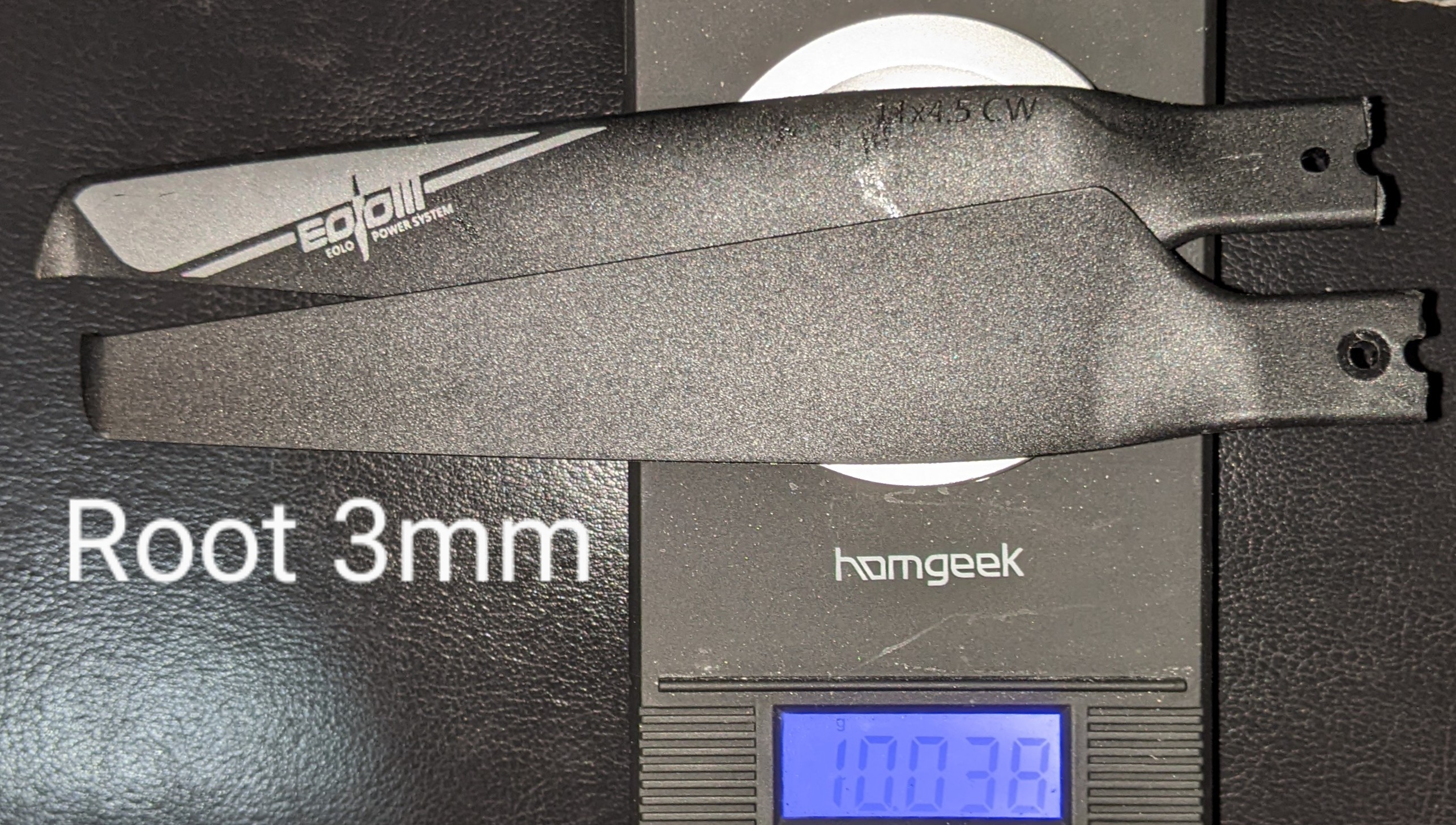
Interchangeable Oxy2 193mm Blades
The Align250 grips can be stretched slightly to accommodate Oxy 193 mm blades' root. The stretched grips holding the blades are considered the standard gripping strength of our production build. But when using Blade 180 (either CFX or Fusion), they need to be thinned using a Lego planning sled, as shown in the following pictures. The router's sled is made of 2 long, thin Lego bricks CA glued to the front plate of the rotary cutting tool. The Hypertough cutting bit, when installed firmly to the end of the rotary tool's chuck, incidentally makes the proper thinning. The bumps of the bricks have gaps smaller than the long sled's width, so that the cravices never catch the sled.


The Lego flat top is well known to give a height increase of about 1.5mm on top of the bumps of bricks. If the cutting bit's shank length is not proper, or if the bricks are augmented with a flat top, the cutting bit needs to be augmented.


The thin flat Lego brick that the blades are glued on can be reused after scraping the glue off.
The final assembly, as tested in the "stock rotor" video, was without the hub-grip-gap washer because a test with the stock washer proved it too tight (with tactile movement during rotation).
T-Motor MN4004 And MN2806 400kv Prototype And Substitute Motors - 42 And 48 Grams Respectively
To prepare the motor for gear-less direct drive, first remove the setscrew(s) of the shaft and clamp the shaft down with a wrench socket spacing beneath the motor bell until the shaft is flush with the motor's top plane. Use a 1/2-inch wrench socket with the 4004 motors. Then, CA-glue a #6 flat-head 1/2 inch machine screw as a pusher on the clamp. Clamp the shaft down the second time with the push rod assembly, as shown in the picture, to remove the stock shaft of the motor. The main shaft is not pressure-fit to the motor but slightly thinner than the original motor shaft. The video here shows that the short bell shaft hole amplifies the thinned diameter, resulting in wobbling.


Interchangeable Microheli 180mm Blades With NACA0012 Airfoil
A pair weighs between 13.4g to 13.6g. Worst case 13.6g. Endurance of 30+ minutes verified here.
Endurance of the substitute Oxy2 193mm blades is shown in the first section discussion of helicopter gyroscopic physics, which has nearly identical endurance for builds with 180mm blades, as shown in the video discussion of Joukowsky 10.5 airfoil of the Converged AIoT chapter, as well as the video on the right with interchangeable NACA0012 blades.
Tail Weight Reduction Alternatives
The original Lynx Blade 230 tail boom is 255 mm long. The replacement 8x7x500mm carbon fiber tube from ebay xzw791 can produce 2 250mm booms. The weight of the replacement is expected to be 4.8g x 250mm / 255mm = 4.7 grams. But the actual weighing has 17.6g / 4 = 4.4 grams. So, the replacement has 0.4 grams weight reduction.

 Countless verifications show no differences in mechanical characteristics and robustness.

 Countless verifications show no differences in mechanical characteristics and robustness.
 |
 |
Motor Stator Rotation Stopper M3 Setscrew 3-5 mm All Interchangeable
The set screw can be tightened after building from the top. 3mm setscrew often comes with 4004 motor bells. 4 mm appears more secure by the look. However, it has been tested with dozens of missions with 3 mm without checking the screw and without any incidence of a loose screw. This is likely because the stopper does not have a consistent direction to loosen to.
Blade Fusion 180 Rotor Counterintuitively Adds Weight
This picture here shows the assembly without the washer if you zoom in to the rotor hub.

When using the Fusion 180 stock rotor, don't use Fusion 180 Smart's DFC link (BLH05805), as they are heavy and easily bent, as shown in the picture below, weighing in at 1.222 g. Instead, use 180 CFX-Trio follower DFC link (aka "original Fusion 180" DFC link, aka BLH3755+BLH3754). When the follower arm is used, turn the servo arms 11 half turns (5.5 full turns) to equalize the length to the production setup with the Infusion 180 DFC links. Every half turn is 0.175 mm in pitch length and is worth 17 us PWM. The weight gain from production parts is (Fusion180 2.93 grips - 0.48 blade bolts + 0.53 blade bolts + 0.81 thrust + 0.89 radial + 1.01*2 + 1.4 hub) - (production 3.7 grips + 0.9 dfc + 0.8 dfc bolt + 1.4 hub) = 1.3 grams. The Fusion 180 grips are about 0.5 grams heavier than production Align grips when bearing and DFC boltings are all included for both; the CFX-Trio follower DFC links are about 0.7 grams heavier when excluding DFC boltings on both.


The 180CFX follower DFC links are designed for a trio blade system, so the phase shift is not aligned with a duo blade system. Trim the phase shift with a cutting disk as follows to get the correct alignment.


The 1.6 mm blade and DFC bolting of Fusion 180 are often bent after a crash. The blade bolting bore holes need to be enlarged by a 1.7mm drill bit, then enlarged again by a 1.8mm drill bit. The DFC bolting just needs generic M1.6 bolts replacement after each crash.


When installing his substitute DFC link, use high torque on generic M1.6 bolting with the bolting stopped by a generic M1.6 washer (quarter mm thin, not the given washer in the kit), and don't use CA glue because it can stick to the rotating parts. The biting of a generic zinc-color-coated M1.6 screw into the thread is never loose with high torque installation. The generic M1.6 bolting allows frequent replacement after any light crashes because M1.6 is weak as expected.
Do not use the flanged washers that are 0.5 mm each and compress the grommet, resulting in a bumpy rotor. Remember, the gap is only 0.5 mm before a rubber grommet that has a 0.25 mm convex. Do trim the Blade 180 feathering shaft less than 0.5mm total as pictured below on the right.


The bumpy rotor with flanged washers compressing grommets is recorded here in videos.
The left side is raw video of the bumpy rotor with flanged washers that PID moderation could not fix between 1:21 and 1:26. The right side is the same bumpy video, but post-stabilized.
Good result with trimming 0.4mm (total) without flanged washers is here. Raw video below on the left is much less bumpy between 0:34 and 0:39. Post-stabilized video on the right.
The true interchangeable Blade 180cfx rotor does not need feathering shaft trimming and naturally has zero slop. But the introduction chapter discussed that it needs more research before mass adoption.
 An experiment on the alternative Align250 carbon-fiber blades are 0.2 grams lighter than Oxy2 nylon blades, and the blade root thickness fits the aluminum Align250 grips. The Align250 aluminum grips are incompatible with Oxy2 blades due to the narrower jaw width.


 TODO: The delta winding motors in the build notes are needed, which adds 0.7 grams. With the above LG batteries, 0.7 + (88.3 - 87.2) = 1.8 grams extra weight. With the Lumenier batteries on the right, 0.7 + (88.3 + 3.4 - 87.2) = 5.2 grams of extra weight. So, the prototype FD411 FC (2.8 g) with ultra-lightweight Runcam HD (7.8 g), analog VTX (1.2g), and alternative tail boom (4.4g) is needed to save 6.5 (HD FC) + 9.6 (1s VTX) + 0.5 (antenna) + 4.8 (boom) - (2.8 + 7.8 + 1.2 + 4.4) = 5.2 grams. Then, verify that the fine-tuned solution mission time is 31.4 * (3000*0.9) / (2*1100*0.9) * 3.45 / 3.7 = 40 minutes.
Production Build Must Adhere To Parts Listing/Build Substitution Notes For Material Properties
 An experiment on the alternative Align250 carbon-fiber blades are 0.2 grams lighter than Oxy2 nylon blades, and the blade root thickness fits the aluminum Align250 grips. The Align250 aluminum grips are incompatible with Oxy2 blades due to the narrower jaw width.
 In the picture below on the left, the upper blade has a pronounced sagging due to a previous experimental test with Align aluminum grip. In that experiment, the blade root was sanded thinner, which softened the material surface. A rapid pitch-up flip at 1:08 in the video below on the right caused a tail strike. Also, the test showed that generic translucent 18-lb zip ties in the tail are not strong enough and break with the tail strike. The part listing's zip tie is stronger than the generic product's nominal tensile strength of 18 lb.

The sagging and tail strike mean that the blade surface should not be sanded to force compatibility, only carved. And this also shows that the production build's Hypertough zip ties can not be replaced with generic zip ties of the same nominal specifications.
Fine-tuning With 2S Li-Ion Batteries
The nominal 650 KV motors can exactly reach our designated 3250 RPM for endurance at the fully discharged 2S 5 V; 650 × 5 = 3250. The actual KV value can be as low as 540 and still reach the optimal RPM near 540 × 5 = 2700, as well as the fast-travel RPM of 540 × 3.18 × 2 = 3430 when the battery is near full charge.


No comments:
Post a Comment