Interchangeable parts are not discussed here; instead, they are mentioned in the original build/operating notes. Here, the substitutes require modifications to installation or operation but otherwise perform the same function. Unviable alternatives are also discussed in this chapter. The entire series of this topic has 8 blogs:
Converged AIoT Developer Kit | Build Notes | Operating Notes | Ground Station Setup | Near The Edge Of Space | Endurance | Weight 250 Grams Breakdown | Build and Operation Substitutes
Sunnysky v4004 300kv motor - 49.2 grams
The M3 antirotation nut is installed then trimmed.


This motor has been verified for diving and racing speeds in the introduction chapter's strap-on battery production section.
The M3 antirotation nut is installed then trimmed.


This motor has been verified for diving and racing speeds in the introduction chapter's strap-on battery production section.


T-Motor 4004 kv400 motor - 48.1 grams
Prototype endurance build.
Prototype endurance build.


The weight of the bell is between 17.3-2.4=14.9 and 17.6-2.5=15.1 grams. The lighter blank stater(22.2g) produces a 32.2g to 32.3g stater. The weight of the stater is very close to the maximum weight of the milligram scale and can damage the milligram scale, hence the multiple weighing on the coarse scale to estimate the true weight. Worst case with the heavier bell and the 0.5g heavier stater(22.7g blank stater) is 32.3+15.1+0.5=47.9 grams. With anti-rotation nut, 48.1 grams.
First, to trim the motor's stater base, preserve the outer ring as a guard against accidental rotary tool slips. Any rotary tool cuts are pre-cuts that don't go through the plate. Then, 6-inch long nose pliers bend along the pre-cut edges, and metal fatigue breaks the material. Trimming the 4004 motor stater saves 36.1-34.8=1.3 grams, as pictured below of the substitute 4004-300kv motor. The 2 pictures also reveal that the 300kv motor is about 2.5 grams heavier than the 400kv motor.

The video here shows the prototype with T-Motor 4004 that used setscrew fitting in short bell shaft hole amplifying the diameter difference between the motor bell bore hole and the main shaft, resulting in wobbling in the prototype build. A single insert strand is only suitable for preventing motor wobble but cannot bond the shaft to the motor bell during operation when the bell rotates with magnetic torque force and the shaft has resistance from rotor aerodynamics.


The weight of the bell is between 17.3-2.4=14.9 and 17.6-2.5=15.1 grams. The lighter blank stater(22.2g) produces a 32.2g to 32.3g stater. The weight of the stater is very close to the maximum weight of the milligram scale and can damage the milligram scale, hence the multiple weighing on the coarse scale to estimate the true weight. Worst case with the heavier bell and the 0.5g heavier stater(22.7g blank stater) is 32.3+15.1+0.5=47.9 grams. With anti-rotation nut, 48.1 grams.
First, to trim the motor's stater base, preserve the outer ring as a guard against accidental rotary tool slips. Any rotary tool cuts are pre-cuts that don't go through the plate. Then, 6-inch long nose pliers bend along the pre-cut edges, and metal fatigue breaks the material. Trimming the 4004 motor stater saves 36.1-34.8=1.3 grams, as pictured below of the substitute 4004-300kv motor. The 2 pictures also reveal that the 300kv motor is about 2.5 grams heavier than the 400kv motor.


The video here shows the prototype with T-Motor 4004 that used setscrew fitting in short bell shaft hole amplifying the diameter difference between the motor bell bore hole and the main shaft, resulting in wobbling in the prototype build. A single insert strand is only suitable for preventing motor wobble but cannot bond the shaft to the motor bell during operation when the bell rotates with magnetic torque force and the shaft has resistance from rotor aerodynamics.
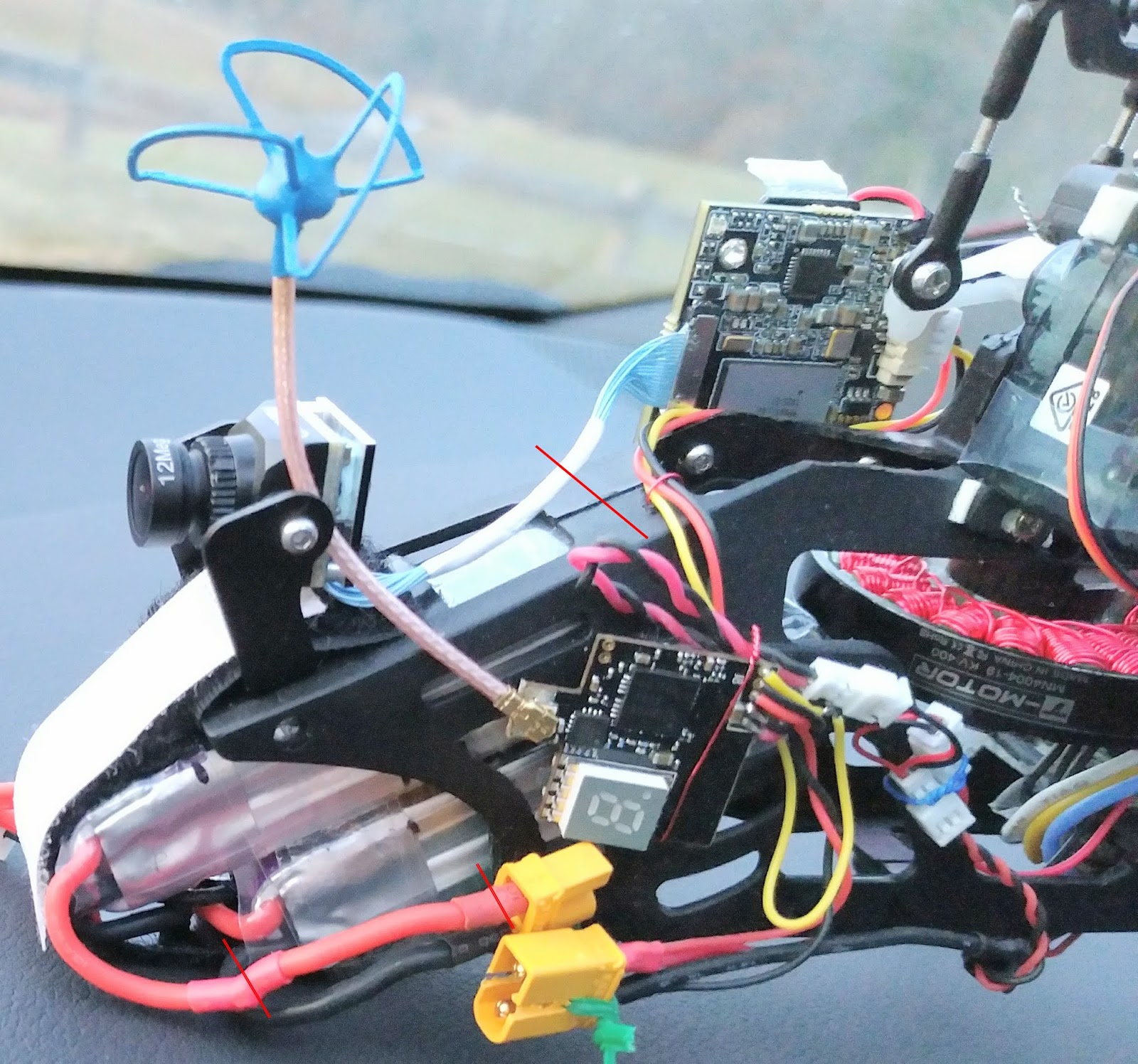
The buck-converter-wire-to-battery-wire ties were permanent for the prototype build and should be Kevlar strings. Solder the short wires to the sides of the main ESC's battery terminals. The production build does not have an external 5-V buck converter and no such tapping.
It is OK for the short wire leads to touch the capacitor between the 2 electrical poles because the capacitor is electrically connected to the 2 poles. To save about 1 gram of weight, tail ESC build needs desoldering the original thick motor wires and replacing them with 4cm of tail motor's lead wires. The newer BLHeli_S or BLHeli_32 with protruding motor solder pads, as seen in the crossed-out in the picture, can not substitute the original BLHeli because the newer ESCs of any model have no RPM governor.
2.png)
Transmitter Setup Wizard
Betaflight does not have a wizard for transmitter setup, and the throttle low limit is the same as other channel's low limit. We manually set all channels' low PWM to 989us even though they can produce 988us PWM because arming code dictates that throttle needs to be lower than the channel's low limit. In LibrePilot wizard, the Collective input value is not isolated when the wizard collects Throttle input value, resulting in a mix-up of the 2 inputs. Our production Converged-AIoT.uav has the fix. It was fixed by manual entering channel numbers after wizard finished its work. The arming dictates that throttle channel needs to be no higher than, neutral level PWM, but low limit needs to be lower than neutral. Librepilot has individual channels' low limits, so, we set low limit to 0 to satisfy the second condition. And we set the neutral to 174 because the throttle output to ESC is scaled from neutral to high. In either case, setting the throttle point closest to actual TX signal's low point gives most precise RPM output.
Betaflight 4.2.5 Aviation Computer HGLRC Forward411 Allows Accidental Disarming Recovery
Avoid Unnecessarily Complicated Disarming Recovery: During the pre-prototype build, the RF controller's arming switch SD (or QX7's equivalent SF) was unnecessarily complicated in the throttle cut mixed into channel 5, as the following 2 graphs.


Channel 5 RPM control bypass means that the aviation computer has no modification on it. So, after a throttle cut, nothing prevents main rotor RPM spoolup if the arming switch is flipped back to high. It is true that a motor mixers of a copter(mmix) require throttle below min_check for arming to be successful and subsequently giving ESC PWM a value anywhere close to 1500us. But our craft doesn't have any motor connected to mmix, instead our main motor is treated as a servo with channel bypass, which takes raw RC throttle input that is not subject to arming manipulation. Further more, collective pitch and cyclic and yaw are a servo mixes, taking RC raw input (source 7) and PIDs outputs, not modified by arming, so, nothing prevents the craft from properly fly and land after an accidental disarm-throttle-cut and uncutting throttle (the upper right cell's condition in the above table). So, the solution is to flip the arm switch back after accidental disarm and land the craft. There is no need for slow spool-up because the on-ground slow-spool-up is meant to prevent blade hitting the ground. Here we are already in the air, away form the ground, and not time for spooling.

However, after uncutting throttle, still disarmed, the stick commands are unpredictable in the air. Our channel 1 throttle is actually collective pitch that is limited in between -23 and 57 points, PWM 1382-1385us to 1785-1792us. Our min_check=1386 and max_check=1886, so only the 8 red-highlighted commands can possibly be activated with low collective pitch when disarmed. And closer look at the remaining 8 commands shows the changes are inconsequential.
The immediate high throttle without slow spool-up risks servo clutch sprain. And in the test video, the descent is faster than usual due to a sprained, slipped servo clutch lowering the collective pitch.
The prototype and production build don't mix disarming into the throttle cut. Again, Channel 5 RPM control bypass means that after accidental disarming, nothing prevents a stable craft from leveling mode and landing as usual. This avoids risking a sprained, slipped servo clutch.
The craft robot was created by humans, but that doesn't mean it is superior to humans and should judge human errors on the RF transmitter commanding RPM to the rotor while disarming the craft. Mixing the motor cut into the arming switch was about that, and it only complicated things further.
The reason the production build's Betaflight 4.5.2 can not do this recovery is because 4.5.2 software disables yaw integral I term when disarmed. So, a failed full rearminig means the tail will rotate continuously.
Nonviable substitution Flywoo F745 Nano Aviation Computer
The F745 Flywoo software has a custom bootup behavior, solving the "twitch" problem of generic F411 software. Due to some difficulties, the difference is persistent from version 4.2.0 through version 4.2.5,. The source code of 4.2.5 may show the branching between F411 and F745 of the difficulties.
.png)

 When fixating the wires, avoid anchoring into the crevasses between the components because the stiff wires can easily damage the components, as illustrated in the picture above on the right. Each wire should be anchored by 2 points on the board to prevent ripping the solder pads. The first anchor is the threading through the tight exit holes. The front wholes are the second anchor for GPS and RF receiver wires. Camera, VTX, Main M1, VBAT-, and S4 wires are glued to a chip flat surface as the second anchor. VBAT+ solder pad is too close to the fixture hole for effective glue anchoring, so its wire uses one extra loop-around on the exit hole as the second anchor.
.jpg)

As pictured on the right, each board fixture whole is capable of allowing seven 1A (26 AWG) wires through, or five 1A wires plus 3 thin servo signal wires. As pictured above, the F745 does not have the flat surface of JST 1mm socket like that in the F411 board. So the rear mount is 3 layers of the clear mounting tape perforated by the array of signal output, with an extra layer of narrow strips front and aft the array of pins. The front mount has a piece of paper to cushion the barometer hole to prevent air sealing. The rear 3 servo signal points are soldered in-place after the board is mounted.
Use the F745 software version 4.2.5 with this configuration .
The Main M1 signal wire appears inadequately short in the pictures due to the alternative fixating of the wire through the bottom side of the board. It should have been on the top side, and there is a good anchoring area on the OSD chip on the top side. Also this alternative fixating makes eight 1A wires through the fixture hole, which is exceedingly tight and a difficult work.
The second behavior difference is the accelerometer startup.
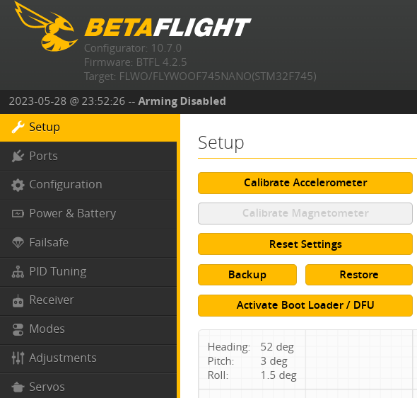
However, even with the Calibrate Accelerometer extra step, the switch-on of the accelerometer during the takeoff procedure can still frequently tip over the craft, 1 out of 5 to 10 tries, as investigated in the video above on the right. The overall difference between F411 and F745 aviation computer configurations is here,
$ diff dump_all_converged_AIoT_hglrc_fd411.txt dump_all_converged_AIoT_flywoo_f7nano.txt
12,14c12,14 < board_name HGLRCF411 < manufacturer_id HGLR < mcu_id 002000503439510f37393937 --- > board_name FLYWOOF745NANO > manufacturer_id FLWO > mcu_id 0044002a3135510731303738 17c17 < # name: HGLRCF411 --- > # name: F7NANO ... hardware pinout differences ommitted here... 270d273 < feature SOFTSERIAL 311,312c314,319 < serial 1 64 115200 57600 0 115200 < serial 30 2048 115200 57600 0 115200 --- > serial 1 64 115200 115200 0 115200 > serial 2 2048 115200 115200 0 115200 > serial 3 0 115200 57600 0 115200 > serial 4 0 115200 57600 0 115200 > serial 5 0 115200 57600 0 115200 > serial 6 0 115200 57600 0 115200 315,318c322,325 < led 0 0,0::C:0 < led 1 0,0::C:0 < led 2 0,0::C:0 < led 3 0,0::C:0 --- > led 0 6,6::CO:8 > led 1 7,6::CO:8 > led 2 8,6::CO:8 > led 3 9,6::CO:8 548c555 < set acc_calibration = 0,0,0,1 --- > set acc_calibration = 0,0,0,0 553,554c560,561 < set mag_bustype = SPI < set mag_i2c_device = 0 --- > set mag_bustype = I2C > set mag_i2c_device = 1 557c564 < set mag_hardware = AUTO --- > set mag_hardware = NONE 560c567 | < set baro_bustype = SPI --- > set baro_bustype = I2C 562c569 < set baro_i2c_device = 0 --- > set baro_i2c_device = 1 609c616 < set blackbox_p_ratio = 32 --- > set blackbox_p_ratio = 16 909d915 < set system_hse_mhz = 8 913c919 < set cpu_overclock = 108MHZ --- > set cpu_overclock = OFF 951c957 < set dashboard_i2c_bus = 0 --- > set dashboard_i2c_bus = 1 964c970 < set flash_spi_bus = 2 --- > set flash_spi_bus = 1 970c976 < set gyro_1_spibus = 1 --- > set gyro_1_spibus = 4 973c979 < set gyro_1_sensor_align = CW0FLIP --- > set gyro_1_sensor_align = CW270 975,976c981,982 < set gyro_1_align_pitch = 1800 < set gyro_1_align_yaw = 0 --- > set gyro_1_align_pitch = 0 > set gyro_1_align_yaw = 2700 978c984 < set gyro_2_spibus = 1 --- > set gyro_2_spibus = 4 990a997,998 > set i2c4_pullup = OFF > set i2c4_overclock = ON 1006c1014 < set name = HGLRCF411 --- > set name = F7NANO |
Nonviable substitution Speedybee F405 Mini 20x20 Aviation Computer
The ICM42688 gyro of the Speedybee F405 Mini requires the Betaflight notch filter to approach, but not match, the stability of BMP2700 and MPU6000 gyro of T-Motor F722 Mini and HGLRC Zeus F722 Mini/HGLRC Forward F411, respectively. The best possible video with Speedybee is here, which has frequent random bumps and twitches.
14-Pole EMAX 2808 660KV Motor
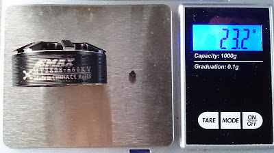
Below first 5 photos are of the same motor. The bell weighs 23.2 grams consistently. The modification to thin wire saves (30.6 + 23.2) - 52.8 = 1g. The 6th photo is of another motor. The stator weighs 52.8-23.2 = 29.6g to 28.7g with thinned lead wires, so 30.6g to 29.7g with original wires. Worst case with stator trimming 30.6 + 23.2 = 53.8 grams.


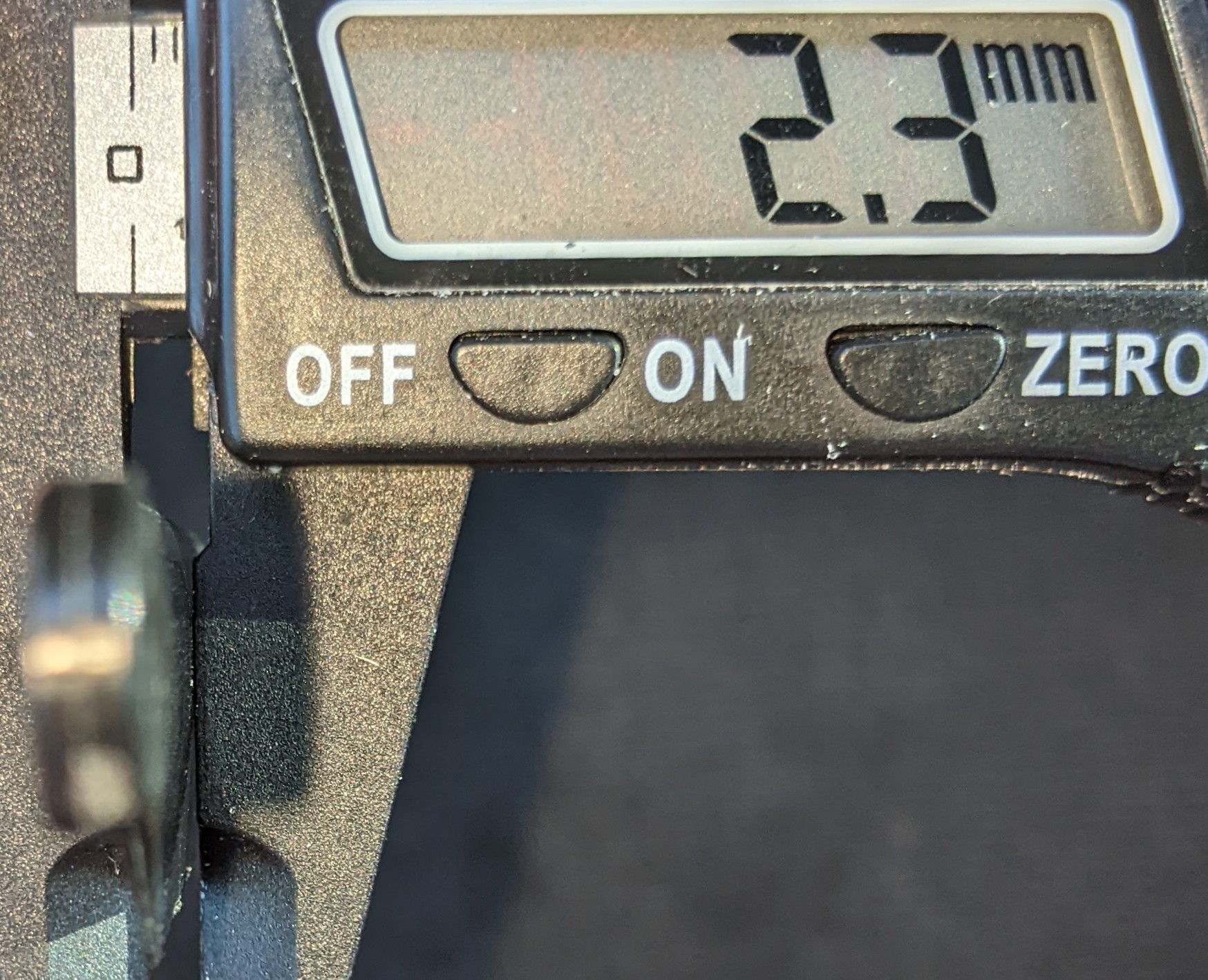
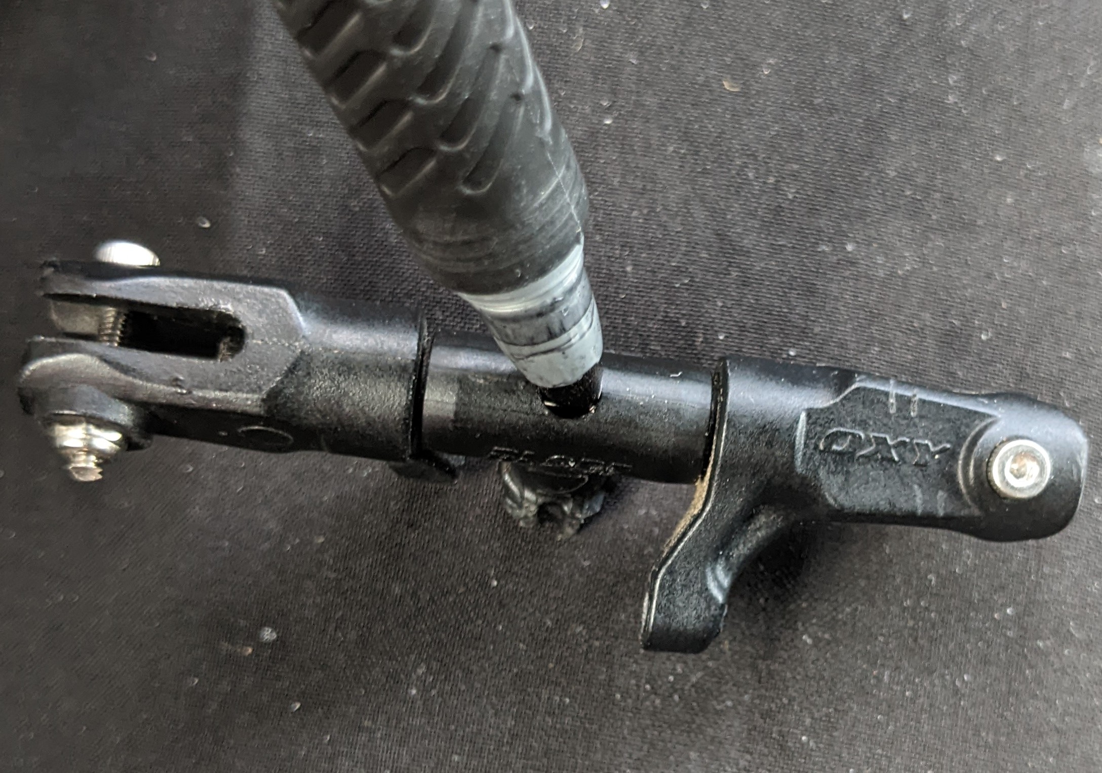
 The 2808 motor stater trimming needs a combination of drills and pre-cuts in contrast to 4004 motors that only need pre-cuts. The outer ring does not need rotary cuts; the pliers bend and pull out the ring sections individually. Trimming the 2808 motor stater saves 33.2 g+0.1 g - 30.6g = 2.7 grams. The trimming of the 2808 motor stator base is mandatory so that the anti-rotation zip tie can thread through beneath the base. So, overall, this alternative motor weighs between 52.8 and 53.8 grams. Looking back at the first picture of this discussion section, Carving out the excess base, trimming out excess wires, and removing the stock shaft save 2.7 + 1.7 + 2.4 = 6.8 grams, resulting in 60.6 - 6.8 = 53.8 grams. The excess wires weigh 1.7 grams. When clamping the shaft down the second time with the push rod assembly, use a 3/8-inch wrench socket with the 2808 motor, as shown below. The 4004 motor and 2808 motor are interchangeable, providing that the 2808 motor has a 0.5mm shaft protrusion at the bottom of the motor, as opposed to the 4004 motor's 2.8mm protrusion The difference of 2.8-0.5=2.3 mm, matching the motor height difference of 21.3-19=2.3 mm.


The 2808 motor stater trimming needs a combination of drills and pre-cuts in contrast to 4004 motors that only need pre-cuts. The outer ring does not need rotary cuts; the pliers bend and pull out the ring sections individually. Trimming the 2808 motor stater saves 33.2 g+0.1 g - 30.6g = 2.7 grams. The trimming of the 2808 motor stator base is mandatory so that the anti-rotation zip tie can thread through beneath the base. So, overall, this alternative motor weighs between 52.8 and 53.8 grams. Looking back at the first picture of this discussion section, Carving out the excess base, trimming out excess wires, and removing the stock shaft save 2.7 + 1.7 + 2.4 = 6.8 grams, resulting in 60.6 - 6.8 = 53.8 grams. The excess wires weigh 1.7 grams.
When clamping the shaft down the second time with the push rod assembly, use a 3/8-inch wrench socket with the 2808 motor, as shown below. The 4004 motor and 2808 motor are interchangeable, providing that the 2808 motor has a 0.5mm shaft protrusion at the bottom of the motor, as opposed to the 4004 motor's 2.8mm protrusion The difference of 2.8-0.5=2.3 mm, matching the motor height difference of 21.3-19=2.3 mm.

 To understand tuning RPM in BLHeli Configurator for the 14-pole 2808 motor, consider increasing RPM by 50 from 2643 to 2693; the new scaling size 981, which produces 50000.0 / 7.0 * 74.0 / 200.0 * 1000.0 / 981.4 = 2693 RPM. So, a 19 PWM change produces a 50 RPM change, a 1 to 2.5 ratio. Also, with the small diameter of the 2808 motor with smaller torque, the fail-safe test video on the right successfully recovered RF control loss with a 2808 motor using ESC governor p-gain 0.5, the same value as the 4004 motor's high punching power setup.
Main motor ESC


To understand tuning RPM in BLHeli Configurator for the 14-pole 2808 motor, consider increasing RPM by 50 from 2643 to 2693; the new scaling size 981, which produces 50000.0 / 7.0 * 74.0 / 200.0 * 1000.0 / 981.4 = 2693 RPM. So, a 19 PWM change produces a 50 RPM change, a 1 to 2.5 ratio. Also, with the small diameter of the 2808 motor with smaller torque, the fail-safe test video on the right successfully recovered RF control loss with a 2808 motor using ESC governor p-gain 0.5, the same value as the 4004 motor's high punching power setup.
Main motor ESC


Align300x Main Grips - 8.5g
They have the same arm span of 12mm as the Align250Pro's grips. They have the same radial bearing spacing and depth as Align250's. But they are longer and can accommodate a thrust bearing at the far side. Unless trimming the main blades, Align250's grip span is too short to accommodate any thrust bearing in-between or at the far side.


The Align300x grips need to be paired with Align300x's hub because the feathering shaft's width is limited to 38.5mm in the market. Overall, this alternative adds a weight of (8.5+2.45-0.3)-(6.2+1.4)=3 grams.


Walksnail Pro Camera
Remove the casing saves 11.271g. Don't use the camera itself that is (5.646+0.981+1.336) = 7.963g. 15.668 - 7.963 + 0.608 = 8.3g.


Spool-up collective pitch angle can be tuned to a smaller angle
But, wait, during spoolup, the aviation mode is manual, the tail motor does not spin, so some negative collective, say -15 points, is required to produce friction between landing skid and the ground to prevent tail spinning. Remember, zero collective pitch doesn't mean zero torque.
Also, if you tune it to very close to 0 points (0 degrees), say -1 point, Betaflight min_check=1386 configuration needs to be raised to min_check=1500 , so that the craft can arm. Remember, whenever RF transmitter is turned on, the -23 points, or, the new -1 point, is activated. And you need to arm the craft at this -23 points or -1 points that is lower than min_check . However, if you actually set min_check to 1500, any slight touch of ANY stick toward low position triggers the stick command(s) as the first picture below because min_check applies to all sticks.


One possible solution for allowing near-zero-collective-pitch-spoolup is to enable computer stabilization during spoolup and disable stick functions all together. But disabling stick functions requires modifying source code of betaflight, and enabling computer stabilization on the ground defeats the purpose of the spoolup-manual mode. Another possibility is to set up the throttle channel 1 as the main motor PWM RF signal, but the aviation stabilization features that are based on throttle channel 1's variation, such as "TPA" and "TPS", can not be used because the helicopter's main rotor RPM is a constant during the mission.
From safety stand point of view, the negative spoolup pitch should be as far from the stick center as possible; from the operation stand point of view, the stick should be as close to the neutral collective pitch as possible.
The only viable possibility is to physically dial up the servo clutch so that PWM 1385 is the neutral position with zero collective pitch. And such alternative needs the collective pitch curve shifted down as above second and third pictures, but still the near-zero-collective-pitch-spoolup's tail spinning problem is not solved.
It is possible to automatically disengage pilot's RPM spoolup
We can use a logical switch in the RF controller to automatically switch on the accelerameter(attitude) mode as soon as the throttle goes higher than -26 (74 out of the 200 points) of 1/4 throttle stick position. But this means that accelerameter(attitude) mode can be downgraded to manual spoolup mode during mission when throttle stick is lower than the 1/4 position. This is due to the fact that logical switches don't have direction awareness whether a craft is taking off or landing. So, pilot would end up needing to be trained to avoid lowering stick to lower than 1/4 position when the craft is in the air in attitude mode in this alternative setup, which can be difficult. One possibility is to use a manual mode throttle curve that reaches spoolup at 1/8 stick. But, still, pilots needs the extra training to avoid lowering stick to 1/8 position. And, the 1/8 position spoolup makes the stick very sensitive to the touch during spoolup.
It is possible to tune the spool-up sensitivity
The 1/4 position full spool up can be changed to 1/8 position with the 9-point throttle curve, which the rotor RPM becomes very touchy and sensitive.
False Alternative Kalman Filter
Neither HGLRC FD411 nor CC3D has the main development branch with Kalman filter. Frequency domain engineering is still the mainstay in the foreseeable future. This is a false alternative.
Five Alternative Battery Packs
650mAh is an alternative that needs alteration of the main frame, trimming out the battery bay ceiling beam, which severely weakens the crash resistance and is unsuitable for adrenaline proximity diving. The crazepony 2S batteries are lighter, 2 packs joined by the trimmed powering wires, not the charging wires.


The GNB packs are heavier and 1mm taller. And the lower jaw of the battery cage needs to be ground 45 degrees at the opening. When the back is installed into the battery compartment, the upper pack is stopped at the wall stud inside the main frame. The pack build uses 18cm of clear tape. The GNB 4S 650mAH, pictured below, does not need the grinding of the main frame.


The RDQ 525mAH, pictured on the right, has the same dimensions as GNB 520mAH but is 0.4 grams heavier.


The XT30 connector can be substituted with EC2 connectors
without adding weight, but EC2 needs clamping tools.

For the FrSky XM Plus receiver with a repairing replacement antenna,
the replacement is about 1 inch longer and it coils around the boom stick for 1 turn.


High-wind FPV landing is risky.
In the above landing approach, I first tilted the head of the craft down so that I could see obstacles around the landing patch on the ground. I continued to keep the head down so that the camera points toward the ground from 0:12 to 0:22 while descending. I ended up facing wind and away from the landing patch because the wind is blowing toward the fence. I flew blindly because I was facing away from the fence and landing patch from 0:22 to 0:30 during final approach. I ripped off the FPV goggles at 0:32 to try to land line-of-sight, but I didn't have the training to fly LOS when the craft flies toward me at the landing target. I was disoriented at 0:37. It crashed.
The appropriate approach planning should be exercised to reduce the risk of landing in high wind as the following table.
The appropriate approach planning should be exercised to reduce the risk of landing in high wind as the following table.
| This is the most favorable condition. Same with landing an airplane. The head wind slows down the craft. The craft elevator tilts downward to resist the wind. At the same time, the FPV camera points toward the ground for clear view of obstacles. With crosswind, unlike an airplane, the drone does not need to change approach heading because the drone flies side ways just as fast as flying forward. So, the craft tilts side ways and forward at the same time FPV camera points toward the ground for clear view of obstacles. With tailwind, without changing approach heading, the craft needs to tilt its head up, pointing FPV camera toward the sky resulting in blind landing. If the pilot heads toward the wind to tilt the FPV camera down to see the ground, he is facing away from the landing patch flying backward blindly as seen in previous crash landing video. The solution is to change heading and convert the tailwind to cross wind. The field of view of the camera only approaches 180 degrees and less, so the side way approach needs a slight forward movement, and the craft lands slightly off the landing target. With tailwind and slight crosswind, the heading should be perpendicular to the wind and heading toward the crosswind component of the wind. The landing target is with in the field of view of the camera. The craft tilts toward the ground to resist the crosswind at the same time the FPV camera points toward the ground for clear view of obstacles. When crosswind mixed with headwind, no heading changes needed because there is no tailwind component to force the pilot to tilt the craft and the FPV camera toward the sky. This is the first and second condition combined. And not heading change needed for either component of the wind. |
Terminal Speed Diving And Punch-Out With 3-Series LiPo Battery
On punch-out, with pre-prototype build of 3S battery and diving at RPM 2607, punch-out with maximum 1666us PWM on ESC and full pitch, airfoil operates as the following diagram.

A workaround for the weak power plant is to maintain the diving collective pitch for a few seconds, after angling the craft for punch-out. as the following airfoil operation diagram.

In such a self-imposed aviation-envelope, at 23 degrees effective angle of attack, the lift slows down the descent enough that the airfoil operating moves to the normal operation region, as the following video, which holds back throttle for 3 seconds at the bottom of the dive after leveling the craft to horizontal. This dive still used RPM 2607.
And with RPM 2607, I can only eliminate the swinging motion by diving with 20 degrees off the vertical line. Terminal vertical speed is 20m/s, as seen in urban diving video, which is significant to the rotor head wind speed, at 42%, 20 to 48 m/s that is calculated in build notes.
AKK IPEX 5.8GHz antenna - 1.2 grams Oxy2 Sport DFC Bolt Set - 1.2 grams
AKK IPEX 5.8GHz antenna - 1.2 grams Oxy2 Sport DFC Bolt Set - 1.2 grams


Dampener
The Rakonkeli CNC delrin dampener is compatible with the 180CFG hub.
The Rakonkeli CNC delrin dampener is compatible with the 180CFG hub.

HD-FPV Camera
Four different powering options have been tested, similar to the FPV camera setup section of the high-performance build post https://nocomputerbutphone.blogspot.com/2018/08/converged-drone-at-edge-of-space.html.
- The MP1584 chip-based buck converters, such as the Bluesky 5V power supply, are the worst for analog video applications.
- The second worst noise interfering with FPV feed is with 12-16V direct battery power supply to the Caddx Turtle cameras (v1, v2, and Baby) in the following video; if you watch the original feed video file https://drive.google.com/file/d/1nL07CPVMDrWu_w7SFtraSYZqxUejrDJr (download it then watch it on a video player instead of watching it online with an online player because online video servers process out the noises to save their internet bandwidth).
- The FPV feed is best clear of interference lines when VTX's 5V aux power filters out low-frequency ripples. However, the market trends move away from VTX aux power and toward pass-thru powering.
- The solution is to share power with servos of the base build, the same as the high-performance build, which has a Wolfwhoop MP2315-chip-based buck converter power supply.

With an extra alternative 10uH inductor, the FPV feed has the video ripple noise level between direct battery power and VTX's aux power in this solution. The ripple noise can not be completely eliminated with a 10uH inductor LC filter because the ripple frequency is similar to or lower than the 10uH inductor working frequency. The ripple noise can not be eliminated with an electrolyte audio A/C capacitor, either, because the ripple frequency, around 1MHz, is much higher than the electrolyte capacitor's audio working frequency.
As pictured on the right, a scrap plastic strut fixture is needed to hold the camera board vertically. Use kevlar strings or enameled wires to tie the board to the strut and craft body. And then, CA glues the fixture arm.Prepare the SD card by sticking it onto a tape with a mounting square, then tear off half of the unused tape. After installing the SD card, fasten the mounting square onto the steel plate of the camera board.


Do not drill holes on the sides of the main frame wall to fasten the camera board because that will weaken the structure and damage the camera wire connectors during a crash. The experiment shows a complete cleavage of the upper main frame when the left side wall is weakened with fastening holes.
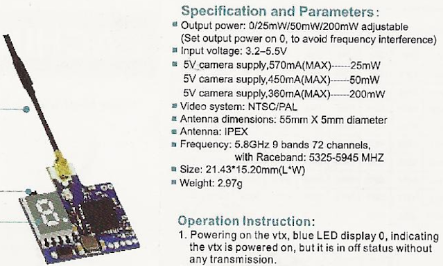
The alternative Eachine VTX03 has AUX power at 360mA, as shown in the specification on the right. It can give the best FPV feed with Caddx Baby Turtle. However, as seen in the following specification comparison, the alternative Runcam Split has a much larger power consumption than the VTX03 can support.


Runcam Split series tapping AUX power of VTX03 results in video freeze with high G maneuver power surges/dips. One incidence of such video freeze is below on the left during punching, where the drone is lost from a considerable altitude.
A second video freeze incident with Split is above the right. If you watch the video to the end, the frozen last frame stays indefinitely after the drone touches the ground.
Substitute T-Motor F722 Mini (US stock fast shipping)
Half and half of all diving videos on the extreme robotics page are with HGLRC Zeus F722 Mini and with T-Motor F722 Mini. The T-Motor aviation computer is 1.4 grams heavier; the Skystar aviation computer is 0.8 grams heavier than the T-Motor aviation computer, still.


 When using the T-Motor F722 mini aviation computer, the servo power tapping and the battery power input switch sides from the production build. This is because the signal bus of the aviation computer is in the mirror orientation between the T-Motor F722 and HGLRC F722, as the following picture shows. This substitute aviation computer is used in many videos in this page.
Aviation software https://drive.google.com/file/d/1pg7u6Lu_YTL9cSmApZCHNXqaG0uHcQiw/view?usp=drive_link
dumpall https://drive.google.com/file/d/1JKzeFYqmqPGFbU8UPpW67yoY2VoHuNzC/view?usp=drive_link
When using this substitute for scientific investigation purposes, the dump_all file differs from the production build in PID sampling rate, gyro logging rate, gyro data filtering mechanism, and GPS algorithm, as follows,
When using this substitute for scientific investigation purposes, the dump_all file differs from the production build in PID sampling rate, gyro logging rate, gyro data filtering mechanism, and GPS algorithm, as follows,
test@penguin:/mnt/chromeos/MyFiles$ diff dump_all_converged_AIoT_HGLRCF722.txt dump_all_converged_AIoT_TMOTORF7.txt
# pinout/timer/dma/servo center/ truncated 510c504 < set gyro_lpf1_static_hz = 0 --- > set gyro_lpf1_static_hz = 125 512c506 < set gyro_lpf2_static_hz = 188 --- > set gyro_lpf2_static_hz = 0 529c523 < set gyro_lpf1_dyn_max_hz = 0 --- > set gyro_lpf1_dyn_max_hz = 500 574c568 < set blackbox_sample_rate = 1/2 --- > set blackbox_sample_rate = 1/4 | # barometer/board/gyro orientation/ibata truncated 672c666 < set gps_ublox_flight_model = AIRBORNE_1G --- > set gps_ublox_flight_model = AIRBORNE_4G 710c704 < set pid_process_denom = 8 --- > set pid_process_denom = 1 714,715c708,709 < set simplified_gyro_filter = OFF < set simplified_gyro_filter_multiplier = 100 --- > set simplified_gyro_filter = ON > set simplified_gyro_filter_multiplier = 50 # camera control/pinio truncated test@penguin:/mnt/chromeos/MyFiles$ |
There is no difference between using lpf1 (my t-motor f722 setup) and lpf2 (my zeus f722 setup). Lpf2 filters before PID loop sampling the craft attitude; lpf1 filters after PID loop sampling, which is a Betaflight software design error. But the advantage of lpf2 is only to quash the aliasing noise frequency at the difference between gyro data sample frequency PID loop frequency. Here the t-motor f722 has no difference between the 2 frequencies - both are 8kHz.
The blackbox_sample_rate of 500 Hz in the production build is sufficient for generating fingerprints for Gyroflow to lock time-matching points.
A test with 125 Hz could not reliably make lockings of time matches. Gyroflow-smoothered video with a 500 Hz logging rate is in many videos of this page.
With the GPS connected to the same power source as the RF control receiver, the GPS power wires are twisted onto the receiver power wires.


This allows GPS to be locked before powering on the craft with the battery. It is suspected to add interference to the gyro with the added active GPS electronics in the first few seconds of booting up the aviation computer, which is the time when the gyro is calibrated by software. However, the test video on the right shows no more yaw drift than the production build's GPS powering scheme.
NACA(NASA) 0015 And 0012 Airfoil Both Capabile Of Terminal Velocity Diving Punch-Out
The airfoil of SP-Oxy2-081 (black graphite nylon) blades and SP-Oxy2-086 (colorful nylon) are NACA 0012 and 0015 airfoils respectively. Search "SP-OXY2-086" or "SP-OXY2-080" is most effective in finding sellers.

NACA 0012 airfoil stalls at 2 degrees earlier in attack angle as ploted here (50,000 Reynold's Number, between aqua color ncrit number 5 and soil color nrit 9).

When punching out of a terminal velocity dive, the collective pitch needs to be delayed. Do not add a collective pitch first because helicopter physics dictates that the craft pitches upward with a positive collective pitch, resulting in stalled movement with a large collective pitch in a high sinking rate. The video on the right (with Sunnysky v2806 400kv motor and 20A ESC) shows the stalled, stumbled punch-out when collective pitch was applied too soon and forceful. The NACA 0012 airfoil punch-out requires more skillful, earlier, subtler cyclic pitch-up to keep the craft borderline stalled while the stall lowers the craft; video footage below on the left. The NACA 0015 airfoil punch-out does not encounter stall by procedure; video footage below on the right.
4-series lipo is required in this procedure. The 3-series Lipo battery punch-out has a different procedure to avoid vortex ring state, discussed in the substitute parts chapter page, not on this page.
Upscaling To 4K For YouTube
The 2 videos are for comparison between uploading 1080p and 4k of the same video. If you watch them both at 720p, you will notice the difference when the craft is near the ground. The 1080p uploaded video has polygon blocks of blurs; the 4k uploaded video is closer to original video.

540p uploading can not improve the polygon blurring, even though it reduces file sizes to 60% of the originals, as shown in the file listing below. The last four entries in the file listing below show that Gyroflow output at 720p can not reduce file sizes; the 30fps file at the bottom fifth listing has file sizes reduced by 25%, not 50%, at the expense of a very choppy viewing experience; Gyroflow produced 100% smooth videos that are more choppy in actual viewing, with only 10% file size reduction in the fourth and fifth listings. The AvatarS0162 and AvatarS0163 are nearly exactly 1 minute each.

.
Substitute Carbon Fiber Fuselage Has Nearly Identical Weight


T-Motor Shaft Work Surface Finishing
 When using T- motor, regardless of the shaft used, the bell rim only needs scraping once, as pictured on the right, because there is no slope of the bore opening like what the Sunnysky motors have.
Vertical Battery Substitute
The Velcro on the battery should only have a slip opening to allow the front wiring to go through. No need to crop the Velcro as the hole only allows the material to stretch and distort.


?
The underside of the craft's protruding Velcro strip needs a backing of another hook Velcro strip to mount the battery. 
Substitute Video Antenna Stiff Tubing
The tubing of the Runcam Link antenna is of a stiff and brittle material. It is too long and can easily damage the coaxial cable. To remove a section of the tubing, use a rotary cutter to score (not cut through) the tubing material into 3 sections and give the middle section longitudinal scoring on 180 degrees opposite sides.


Once scored, the 3 seconds can be separated by hand, and the middle section can be crushed and split by pliers gripping at an off angle from 180 degrees.
Some sales of the 9cm video bus cable include a plate that needs to be removed. The plate is of molded metal and can be cracked with pliers (no rotary cutting needed). The video computer board uses 3 ziptie mount points. The lower aft ziptie needs pre-bending.

 Plastic housing borehole of Walksnail Avatar 1S is only drilled diagonally from the factory. Drill the missing upper left hole with a 1.1 mm bit, so that a Kevlar string can be tied to fasten the camera onto the zip tie.
Use Skystar Mini F4 Aviation Computer For Single Solder Scheme
 When using T- motor, regardless of the shaft used, the bell rim only needs scraping once, as pictured on the right, because there is no slope of the bore opening like what the Sunnysky motors have.
 Vertical Battery Substitute
The Velcro on the battery should only have a slip opening to allow the front wiring to go through. No need to crop the Velcro as the hole only allows the material to stretch and distort.


?
The underside of the craft's protruding Velcro strip needs a backing of another hook Velcro strip to mount the battery.

Substitute Video Antenna Stiff Tubing
The tubing of the Runcam Link antenna is of a stiff and brittle material. It is too long and can easily damage the coaxial cable. To remove a section of the tubing, use a rotary cutter to score (not cut through) the tubing material into 3 sections and give the middle section longitudinal scoring on 180 degrees opposite sides.


Once scored, the 3 seconds can be separated by hand, and the middle section can be crushed and split by pliers gripping at an off angle from 180 degrees.
Some sales of the 9cm video bus cable include a plate that needs to be removed. The plate is of molded metal and can be cracked with pliers (no rotary cutting needed). The video computer board uses 3 ziptie mount points. The lower aft ziptie needs pre-bending.


Plastic housing borehole of Walksnail Avatar 1S is only drilled diagonally from the factory. Drill the missing upper left hole with a 1.1 mm bit, so that a Kevlar string can be tied to fasten the camera onto the zip tie.
Use Skystar Mini F4 Aviation Computer For Single Solder Scheme
Thrust Bearing Complicates Building
The good dives are reproducible consistently using Oxy2 grips, which have thrust bearings pictured here. 
 When installing the Oxy2 grips, watch out for factory assembly mistakes that occur about once every 10 pieces by the tentative(without washers and without hard cranking) installation of the feathering shaft and pulling, as shown in the following video on the. But, first use a marker to mark a dot to make sure, if the pulled grip rotates smoothly by itself or by rotating the shaft and the other grip's bearing provides the smoothness. A correctly assembled grip set should feel surprisingly and pleasantly slick in the pulling test on both grips.
The technique in the following left-side video is incorrect because a good grip on one side can ensure a smooth rotation on the other side, masking the problem of one-sided manufacturing mistakes. The following right-side video shows the entire assembly process.
The factory assembly sometimes misplaces a high-error inner thrust disk instead of the low-tolerance outer thrust disk, as explained in the video above on the right. Discard the bad grip. The outer thrust disk needs to hug the feather shaft tightly because the radial bearing's inner tube needs to rest on the outer thrust disk without sinking into the crevice between the shaft and the disk, which would result in transferring centripetal, axial force onto the junction between the outer radial bearing's inner and outer tube. The general AIoT kit build uses Align250 main grips without thrust bearings to avoid the added build complexity.
The good dives are reproducible consistently using Oxy2 grips, which have thrust bearings pictured here.


When installing the Oxy2 grips, watch out for factory assembly mistakes that occur about once every 10 pieces by the tentative(without washers and without hard cranking) installation of the feathering shaft and pulling, as shown in the following video on the. But, first use a marker to mark a dot to make sure, if the pulled grip rotates smoothly by itself or by rotating the shaft and the other grip's bearing provides the smoothness. A correctly assembled grip set should feel surprisingly and pleasantly slick in the pulling test on both grips.
The technique in the following left-side video is incorrect because a good grip on one side can ensure a smooth rotation on the other side, masking the problem of one-sided manufacturing mistakes. The following right-side video shows the entire assembly process.
The factory assembly sometimes misplaces a high-error inner thrust disk instead of the low-tolerance outer thrust disk, as explained in the video above on the right. Discard the bad grip. The outer thrust disk needs to hug the feather shaft tightly because the radial bearing's inner tube needs to rest on the outer thrust disk without sinking into the crevice between the shaft and the disk, which would result in transferring centripetal, axial force onto the junction between the outer radial bearing's inner and outer tube. The general AIoT kit build uses Align250 main grips without thrust bearings to avoid the added build complexity.
Chromebook Dual Boot Xubuntu
A dual-boot Xubuntu installation on the Chromebook's internal disk partition "STATEFUL" that runs the configurator stand-alone well is documented on the American Way Of Computing blog. The AMD64 binary is downloaded from https://github.com/blheli-configurator/blheli-configurator/releases.
Bare-metal Xubuntu Gyroflow GPU renders HD footage 30% faster than the extreme robotics build, as shown in the following picture. Also, as shown in the picture, the dual-boot Xubuntu only needs to manually install 1 package, Qt6, unlike the Chromebook Linux, which requires manually installing 5 packages.
CPU rendering is often cited as producing higher-quality results. In a real-world side-by-side comparison here, there is no perceivable difference.
A dual-boot Xubuntu installation on the Chromebook's internal disk partition "STATEFUL" that runs the configurator stand-alone well is documented on the American Way Of Computing blog. The AMD64 binary is downloaded from https://github.com/blheli-configurator/blheli-configurator/releases.
Bare-metal Xubuntu Gyroflow GPU renders HD footage 30% faster than the extreme robotics build, as shown in the following picture.

Also, as shown in the picture, the dual-boot Xubuntu only needs to manually install 1 package, Qt6, unlike the Chromebook Linux, which requires manually installing 5 packages.
CPU rendering is often cited as producing higher-quality results. In a real-world side-by-side comparison here, there is no perceivable difference.
No comments:
Post a Comment