Antenna Cluster Planning
 For vertical diving proximity, use 3-D modeling of the mission scenario sketch. The example with Blender is in the picture on the right. The small matchbox at the lower left corner is the base station. And, based on the mission scenario, the RF-control/FPV antennas are arranged to prevent internal interference and obstructions.
For surface proximity, ground obstacles were viewed in mapping software.
Zooming in reveals an extra outcrop of rocks blocking LOS of the 1km proximity site. The land survey revealed a radio LOS dead zone packet during low tides.

The aerial survey avoided the dead zones with large margin accordingly.
However, during the actual proximity mission, the high tide prompted acute piloting toward the land. Without an on-location survey, the proximity mission during high tide failed (drone loss in the sea) with altered path obstacles.
The high-tide view of the crash site immediately after the craft loss shows no sandy shoreline.
The rendezvous plan record was photographed immediately after the crash. Actual dive at 6336, 6090 by memory.

The view of the ground station is used to identify the on-location perspectives.


On-location perspective and tracing the path of the blocking obstacle were identified at the location of the crash.
The failed mission path and the original planned path were plotted.
The off-course path on-location perspective is identified next to the original planned (unblocked) one.
The large rock is a reliable visual landmark (unblocked) after a storm eroded sand and displaced pebble stones.
Then, the proximity mission succeeded in the next attempt.

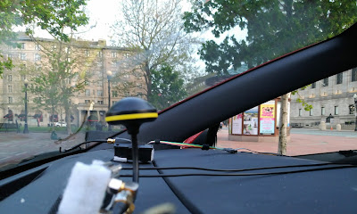
The in-car battery and VRX were under a white food bag to cool them in the sun during the mission.
RF Transmitter Setup
The alternative micro sized transmitter module wiring pictured here.
The alternative Frsky R9M module can be set to output 500mW using alternative Taranis QX7's transmitter's regular power pins without external power source, as shown in this video,
This flight sequence rehearses the mission plan, diving from 330 feet east, 440 feet north, ground distance 550 feet, air distance 1000 feet, relative to ground station. 3 flips above the landing patch area. Level traversal between 330 feet east, 440 feet north, and 330 feet straight east.
This flight sequence rehearses the mission plan, diving from 330 feet east, 440 feet north, ground distance 550 feet, air distance 1000 feet, relative to ground station. 3 flips above the landing patch area. Level traversal between 330 feet east, 440 feet north, and 330 feet straight east.
Video Receiver Setup

The brand-new VRX cost is here.
In-Car Battery Charging
Fight batteries should be warmed/cooled with car vent before charging in cold/hot temperatures. When the car engine is offline, the car battery voltage has a slight drop, so the flight battery charger needs to be set to output below 1 amp to prevent low low-voltage cut-off during charging. The charger wires are hung by velcro stripes without a sticky backing.
TalentCell power bank YB1206000-USB has overheating protection. Keep it on the dashboard and plug in the charging plug year-round. If it is overheated by the sun, wait until it cools down to power on.
Walksnail 1S Lite USB Adapter Compatible With HD V2 Cameras.
As long as the plug is aligned with the socket to the left most pin when viewing from the right side of the craft toward the left side of the craft.
Box 17.5 Inches Long And 3 Inches Thick Or Larger
Cut the cardboard by the green line and the seam line pointed by the arrow, cutting the box in half while keeping a lid.


FPV Feed Flight Path Tracking
The raw FPV DVR recorded mp4 of the tail-spin crash with fishbowl optical illusion is saved at googledrive https://drive.google.com/file/d/1IchzErZsqhmW0qukS_ZLuJz3CpO4A27t .
When viewed in Android MX Player or the FPV headset, the last 3 frames used to track down the wreckage is not available frame-by-frame. A laptop or Chromebook with Avidemux.AppImage is needed to step in the last 3 frames.
Avsaase/walksnail-osd-tool From Github
Compatible with Chromebook for crash GPS searching with frame-by-frame video of a crash.
Anthwlock/untrunc From Github
Compatible with Chromebook for crash-interrupted VRX .mp4 file un-corrupting. The code is based on original ponchio/untrunc that has bug compatibility with Chromebook.
  248  git clone --recurse-submodules https://github.com/ponchio/untrunc
  249  cd untrunc
  250  vim ../untrunc-master/README.md
  251  ls
  252  cd libav/
  253  ls
  254  ./configure
  255  sudo apt install yasm wget
  256  ./configure
  257  make FF_VER=3.3.9
  258  vim ../untrunc-master/README.md
  259  cd ../
  260  vim ../untrunc-master/README.md
  261  grep g++ ../untrunc-master/README.md
  262  vim ../untrunc-master/README.md
  263  g++ -o untrunc -I./libav file.cpp main.cpp track.cpp atom.cpp codec_*.cpp codecstats.cpp codec.cpp mp4.cpp log.cpp
-L./libav/libavformat -lavformat -L./libav/libavcodec -lavcodec -L./libav/libavresample -lavresample -L./libav/libavutil
-lavutil -lpthread -lz -std=c++11
  264  sudo cp untrunc /usr/local/bin
  265  which untrunc
  266  untrunc
  305  cd ../../
  306  cd MyFiles/Downloads/
  307  untrunc ./AvatarS0086.mp4 ./AvatarS0087.mp4


